Worm Gear Machining: The Mesh Is Three Numbers
A worm gearbox is one of the quietest ways to get a big reduction out of one stage. It is also one of the easiest to get wrong, and when it is wrong the symptom shows up eighteen months later as a howl from a machine that nobody wants to open up. The teeth are usually not the problem. The problem is that a worm and a wheel are not two parts; they are one mesh, and the mesh is created by three numbers that live in three different places on the drawing: the lead of the thread on the shaft, the helix of the teeth in the bronze rim, and the distance between two bored holes in the housing.
This article is about machining that set. It covers the worm shaft, the bronze wheel, the housing that carries both, the materials each one is made from, the order the operations should run in, and the checks that tell you the mesh is right before the box is closed. It is written for the shop that gets asked to make the parts, and for the buyer who has to decide whether to make them or buy the pair.
What a Worm Drive Actually Is
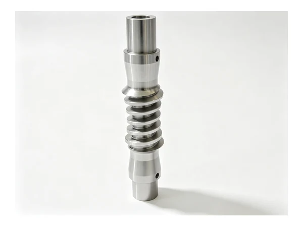
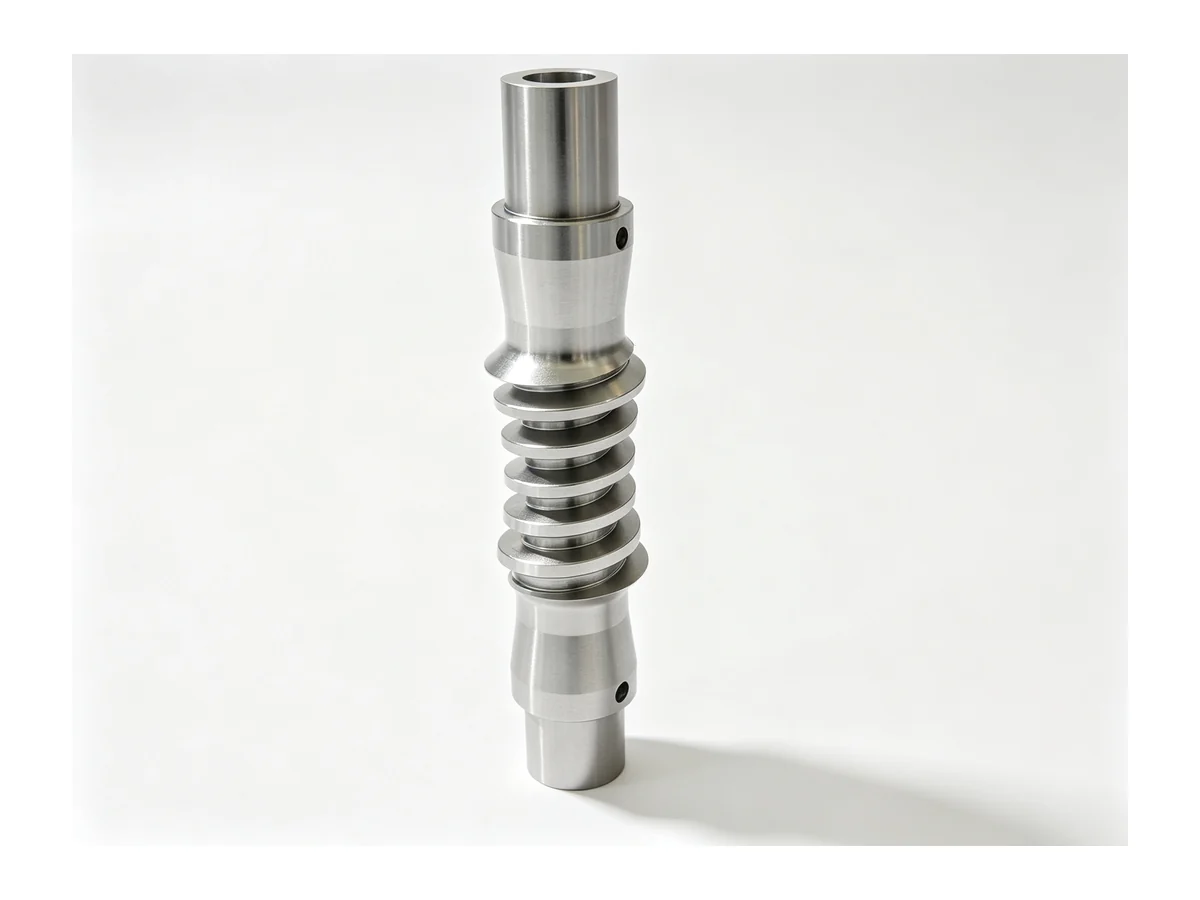
A worm drive is a screw meshing with a gear. The screw, called the worm, has one or more continuous threads wrapped around a cylinder. The gear, called the worm wheel, has teeth cut on a rim that is usually bronze. The worm drives the wheel, the wheel is on the output shaft, and one turn of the worm advances the wheel by one tooth. That is why a single stage gives between five and a hundred to one without a second pair of gears, and why the arrangement fits in a box the size of a shoebox.
The contact between the two is sliding, not rolling. Every other gear type rolls its teeth together; a worm slides along the wheel flank the whole time it is in mesh. That single fact explains most of the machining consequences. Sliding contact needs a hard worm and a soft wheel, because the soft one is meant to wear. It needs oil, because there is no oil film built by rolling. It runs hot, because sliding generates heat. And it can be made self-locking: at a low lead angle the wheel cannot drive the worm back, which is why worm boxes appear on hoists, gate drives, positioners and anything that must hold its position with the motor off.
Two shapes exist. A cylindrical worm is a plain screw; its wheel is throated, meaning the rim is concave so it wraps part of the worm. A globoid worm is barrel-shaped, larger in the middle than at the ends, and it wraps the wheel instead. The globoid form carries more load in the same space and is harder to make, because the thread is cut on a curved axis. For most industrial gearboxes the cylindrical worm with a throated wheel is the standard, and it is what the rest of this article assumes.
The Three Numbers That Decide Whether It Runs Quiet
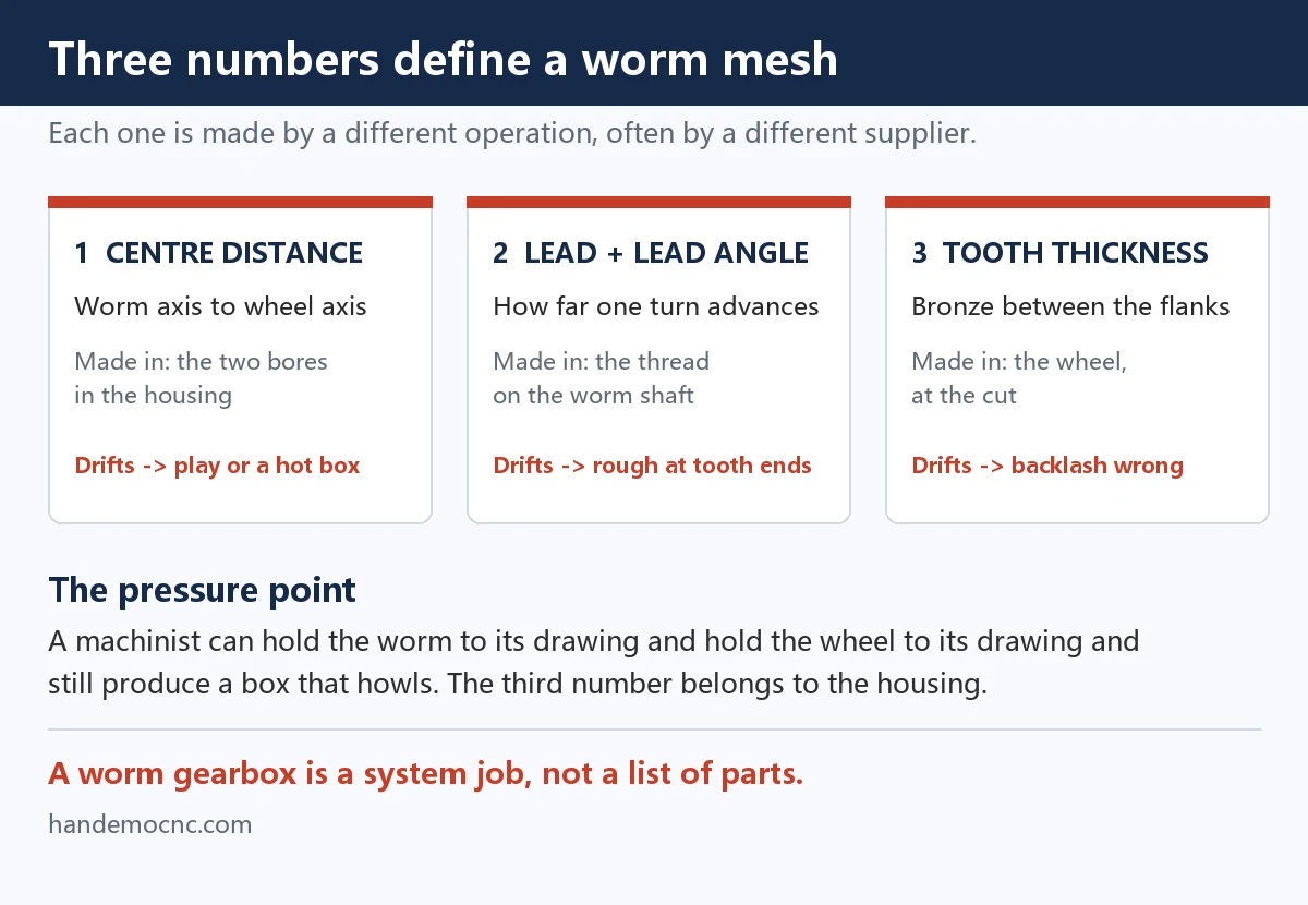
Every worm box is defined by three quantities. Each one is created in a different operation, by a different machine, often by a different supplier. When a box howls or runs hot or develops play, one of these three moved.
| Number | What it is | Where it is made | What happens when it drifts |
|---|---|---|---|
| Centre distance | The distance between the worm axis and the wheel axis | The two bored holes in the housing, cut in one setup | Too far and the mesh is loose: play at the output, impact on every reversal. Too close and the mesh is tight: heat, noise, bronze worn away in the first week |
| Lead and lead angle | How far one turn of the thread advances, and the angle that thread makes with the axis | The thread on the worm shaft | A lead error spreads over the whole face of the wheel; the drive runs smooth in the middle of the tooth and rough at the ends |
| Tooth thickness | How much bronze sits between the flanks of the wheel teeth | The wheel, at the moment it is cut | Sets the backlash. Cut it thick and the box is tight; cut it thin and the box rattles and the teeth are weaker |
Note where the pressure sits. A machinist can hold the worm to a drawing and hold the wheel to a drawing and still produce a box that howls, because the third number, centre distance, belongs to the housing. This is why a worm gearbox is a system job and not a list of parts. Any shop that quotes the shaft and the wheel without asking who bores the housing is quoting half a gearbox.
Machining the Worm Shaft
The worm shaft is a turning job with one awkward feature on it. Everything except the thread is ordinary lathe work: bearing journals at both ends, a seal land, a coupling or a spline, maybe a cross hole for a pin. The thread in the middle is the part that decides whether the job was done well.
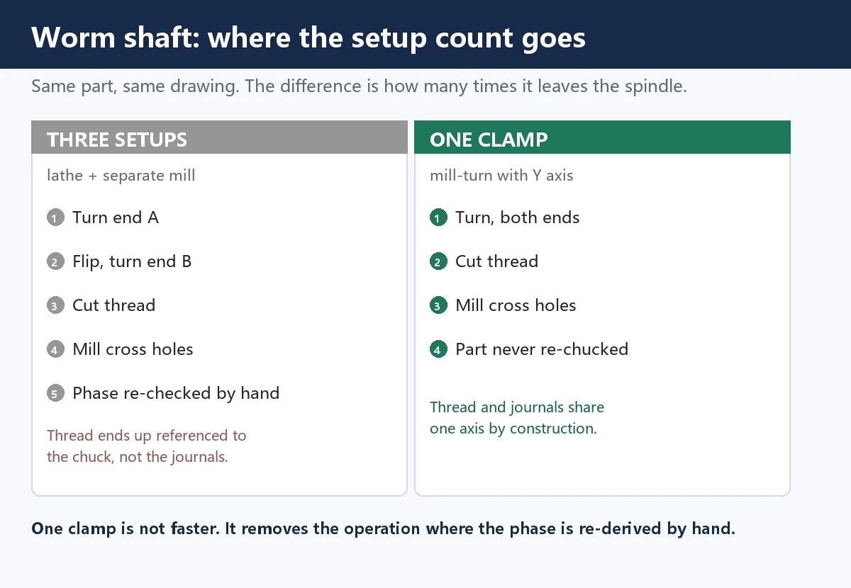
The usual route is three setups. Turn one end, including its journal and shoulder, then flip and turn the other end, then cut the thread. That route works, and it has a structural weakness: every flip re-establishes the relationship between the thread and the bearing journals by hand, with a chuck and an indicator. The thread ends up slightly off the axis that the bearings will actually run on, and the mesh pays for it with a contact pattern that sits on one flank instead of across the face.
The route that removes the weakness is one clamp. On a lathe with a live tool turret and a Y axis, the shaft is turned between centres or held in a chuck with a tailstock, all journals are cut, and then the same turret picks up a thread milling cutter or a thread insert and cuts the thread without the part ever leaving the spindle. The relationship between the thread and the journals becomes a property of the machine rather than of the operator's hands.
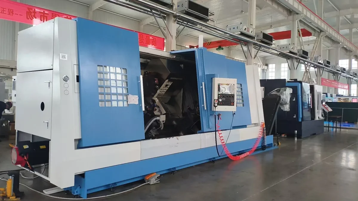
That is the case for a machine like the 70Y series mill-turn lathe. The range covers 1,000, 1,500, 2,000 and 3,000 mm of maximum cutting length on the same bed design, with an A2-8 spindle nose and an 85 mm bore, speeds to 3,000 rpm and a Y axis that travels 75 mm either side of centre. The Y travel is what makes the thread possible, because a thread milled on the centre line alone cannot clear the flank of a coarse multi-start thread. For shorter worms, the TCK56Y covers 400 to 930 mm of cutting length on an A2-6 nose with a 65 mm bore.
Three ways to cut the thread, and when each one makes sense
Single-point threading with an insert is the cheapest and the slowest. It works for fine pitches and for single-start worms where the thread is shallow. On a coarse multi-start worm the insert has to be fed in and out for each start, and the phase between the starts is set by the control's index, which is fine on a new machine and progressively less fine on a worn one.
Thread milling with a disc or a full-profile cutter is the general-purpose answer on a mill-turn. The cutter is smaller than the thread, it runs around the helix with the C axis interpolated against Z, and the thread can be cut in one continuous pass from end to end. Because the cutter approaches from the side, the flank angle comes from the tool and the lead comes from the motion, which is the right split: the tool is a purchased item that can be checked, the motion is the machine's job.
Whirling is the production answer. A ring of cutters surrounds the shaft and the head feeds along it while the work rotates slowly. It removes material fast, it handles long worms without the deflection a single-point tool would suffer at the middle of a two-metre shaft, and it is the method behind most commercial worm shafts. It is also a dedicated machine, so it belongs to the shop that makes worms every week, not the shop that makes one.
Multi-start worms: the phase is the job
A two-start worm has two threads that begin 180 degrees apart. A three-start has three at 120 degrees. The pitch of each thread is the same; what changes is how many threads are packed into the same length, and therefore how far one turn advances the wheel. Get the phase right and the wheel sees two identical contacts per revolution. Get it wrong by a few degrees and one thread carries everything while the other idles, which shows up as a box that is noisy at light load and quiet at heavy load, or the other way round.
This is why the indexing has to be done in the same clamp as the thread itself, and why a worm shaft should never be re-chucked between starts. If the machine cannot index the spindle under control, the job belongs on a machine that can, or on a thread grinder that cuts all starts from one setting.
Machining the Worm Wheel
The wheel looks like a gear and is cut like one, with one difference that catches people out: the cutter must be the worm. A hob for a worm wheel is a replica of the worm with gashes and relief cut into it. It cuts the wheel with the same profile the worm will present, which means the wheel cannot be cut before the worm is finished, and a replacement wheel cannot be cut by anyone who does not have the worm in hand.
On a hobbing machine the wheel rotates in mesh with the hob while the hob feeds tangentially. That is a geared relationship: two rotations tied together by the machine's train. It is fast, it produces a throated form correctly, and it is what a gear shop will do for any quantity above a handful.
On a machining centre with a fourth axis, you can cut a wheel by indexing tooth by tooth with a form cutter or by milling each tooth with a small end mill following the flank. This is slow, and the throat has to be interpolated rather than generated, but for one or two wheels it is often the only route a general machine shop has. The honest limit is that a wheel cut this way needs to be run in against its own worm before it is quiet, because the contact is a series of milled facets rather than a generated surface.
The bronze rim and the steel hub
Most industrial wheels are not solid bronze. They are a bronze rim shrunk or bolted onto a steel or cast iron hub, because bronze is expensive and because the hub has to carry the key and the output shaft. The rim is turned as a ring first, with the bore and the faces done in one clamp so the rim thickness is even all round, then fitted to the hub and finished. If the rim is machined after fitting, the tooth cut and the hub bore share one axis, which is what the mesh needs. If it is machined before fitting, the shrink fit has to be checked for tilt, and any tilt becomes a wheel that runs out of true once per revolution.
The throat, the concave curve across the face of the rim, is turned. On a lathe with a form tool or with a interpolated arc, the rim is cut to a radius slightly larger than the worm so the contact starts in the middle of the face and spreads outward as the box wears in. Cutting the throat to the exact worm radius gives a wheel that contacts across the full face from the first minute, runs hot, and wears a step. The extra clearance is deliberate.
The Housing Is Part of the Gearbox
Two bores, one for the worm bearings and one for the wheel shaft, at a fixed distance, on parallel axes, in a casting that is often not much thicker than the bearings it holds. In a small box the two bores are usually cut on a horizontal machining centre in one setup, because the alternative — boring one side, flipping, boring the other — puts the centre distance at the mercy of the flip.
There is a second reason to cut them together. The worm axis and the wheel axis have to be at right angles and in the same plane. If they are bored from opposite faces, a small squareness error tilts the worm in the box and the contact pattern moves to one end of the wheel face. The box then runs quiet in one direction of rotation and noisy in the other, which is a classic symptom that gets misdiagnosed as a bad wheel.
On a horizontal with a rotary table, the pattern is: bore the worm side, index the table 90 degrees, bore the wheel side, and both holes come off the same spindle in the same clamp. On a vertical, the same job needs an angle plate and two setups, and the second setup is where the error enters. For boxes large enough to need a boring mill, the same logic applies at a bigger scale. The guide to machining box and housing parts covers the machine choice in more detail.
Assembly is the last chance to correct the mesh. Measure the actual pair, measure the actual bore spacing, and if the box has an eccentric bearing carrier or a shimmed bearing housing, set the centre distance at assembly rather than trusting the bore. A box that can be shimmed is a box that can be made quiet with a real wheel and a real worm in it.
Materials, and What Each One Does to the Cut
The material pairing is not a matter of preference. The worm is hard and the wheel is soft, and that relationship is what makes the drive survive.
Worms are cut from case-hardening steels such as 20CrMnTi and 17CrNiMo6, or from through-hardening steels such as 42CrMo4 and 40Cr. Case-hardened worms are usually cut soft, hardened, and then ground, because the heat treatment moves the thread and there is no way to hold the lead through it otherwise. For light duty and for shafts where wear is not the issue, the thread can be cut and left as cut, which is cheaper and perfectly adequate on a hand-driven gate or a low-speed indexer.
Wheels are cut from tin bronze: ZCuSn10P1 and CuSn12 are the common grades, with aluminium bronze such as CuAl10Fe3 appearing where the load is shock rather than steady. Cast iron appears on light, slow, cheap drives where noise does not matter and life is measured in years of occasional use. Stainless worms show up in food, pharmaceutical and washdown equipment, and they change the cutting more than the design.
| Part | Typical material | How it is cut | What to watch |
|---|---|---|---|
| Worm, general duty | 42CrMo4, 40Cr | Turned, thread milled, induction hardened, sometimes ground | Hardening distortion in the thread; grind after, not before |
| Worm, high duty | 20CrMnTi, 17CrNiMo6 | Turned, thread milled soft, carburized, thread ground | Leave grinding stock on the flank, not on the crest |
| Wheel rim | ZCuSn10P1, CuSn12 | Ring turned, fitted, hobbed or milled, run in | Bronze tears if the edge is dull; sharp tools only |
| Wheel rim, shock load | CuAl10Fe3 aluminium bronze | Hobbed with carbide, slower speeds | Abrasive chips; keep the coolant clean and filtered |
| Housing | GG25, HT250 cast iron | Bored on HMC or boring mill, both axes one setup | Cast skin hard spots deflect a boring bar |
Cutting bronze without tearing it
Bronze is soft, and soft does not mean easy. A dull edge rubs instead of cutting, the surface work-hardens under the rub, and the next pass tears. On a wheel rim the tear appears on the flank of the tooth and is invisible until the box is assembled and run, at which point it becomes a wear site. The rules are simple: sharp carbide with a positive rake, no dwell in the cut, climb milling on the finishing pass, and enough coolant to carry the chips away rather than recirculate them.
Aluminium bronze is the exception in the other direction. It work-hardens fast, it is abrasive, and it will destroy an insert that would cut tin bronze all day. Slower surface speed, heavier feed per tooth so the edge stays under the hardened layer, and a coolant system that actually filters are what keep it predictable.
Inspecting the Mesh Before the Box Is Closed
Most shops making worm parts do not own a gear tester, and they do not need one for the checks that matter. Four checks catch nearly everything.
The first is the contact pattern. Assemble the pair in the housing with marking compound on the worm, turn it through a few revolutions by hand under light drag, and look at where the blue transfers onto the wheel. The pattern should sit slightly toward the leaving side of the tooth and cover most of the face height. A pattern on one end of the face means the axes are not in the same plane. A pattern in a narrow band across the middle means the throat radius is wrong.
The second is backlash, measured by holding the worm still and rocking the wheel with an indicator on a tooth. This is the number the customer will feel, and it is set by tooth thickness and centre distance together.
The third is the lead, checked by running an indicator along the flank while the shaft is rotated through several turns. The reading should progress evenly. A step in the reading means the thread was cut in more than one pass with the phase lost between them.
The fourth is a run-in. Run the box light for half an hour, drain, and look at the oil. A little bronze glitter is normal on a new wheel. Chunks, or a grey paste, are not.
When to Buy the Pair Instead of Cutting It
There is a point where making the parts costs more than buying them, and it arrives earlier than most shops expect. A standard worm box in a cast housing, in a common ratio, is a commodity item produced in volumes that no job shop can approach. Cutting the worm and the wheel for one replacement unit means buying or making a hob, cutting a bronze rim, and running in a pair that has no history.
Machining makes sense in four situations: the ratio or the centre distance is not standard; the housing is part of a larger weldment or casting that has to be machined anyway; the environment rules out a catalogue box, for example washdown, high ambient temperature or a food area; or the volume is high enough that a dedicated pair pays for its tooling. Outside those, the engineering answer is to buy the pair and machine the housing to suit, which is also the answer that gets a machine back into production fastest.
If you are the buyer, the question to ask your supplier is not "can you cut a worm wheel" but "do you cut the wheel with a hob made from my worm". The answer separates a gear shop from a machine shop that owns a fourth axis.
FAQ
Can a worm and wheel be made as separate parts by different suppliers?
Only if both are cut to the same defined geometry, including the worm's actual measured lead and profile rather than its nominal drawing. In practice, a wheel cut to a nominal worm and run against a real worm from another source will contact on one flank and wear in a pattern nobody planned. The safe route is one supplier for the pair, or a wheel cut with a hob made from the finished worm.
Why does my gearbox run quiet one way and noisy the other?
Almost always the squareness of the two bores in the housing. If the worm axis is tilted relative to the wheel axis, the contact pattern sits toward one end of the wheel face, and reversing the drive loads the opposite flank at a different point on that tilt. Check the housing before blaming the wheel.
Do I need a mill-turn machine to cut a worm shaft?
No, but it removes a setup. A lathe with a thread insert, plus a separate operation for cross holes and flats, will produce a serviceable worm. The mill-turn earns its place when the shaft is long, when it carries milled features that must be phased to the thread, or when the volume makes the extra handling visible in the cost per part.
How many starts should a worm have?
One start gives the highest reduction and the self-locking behaviour, at the cost of efficiency. Two or three starts give a faster output and better efficiency for the same centre distance, and give up self-locking. Four starts and above are for drives where speed matters more than reduction. The choice is made at design, not at the machine.
What causes a bronze wheel to wear out in months instead of years?
Three usual causes: the wrong oil or a low oil level, a mesh that is too tight because the centre distance closed up, or a worm that was hardened but not ground, so its thread still carries the marks of the cutter. The last one is common on low-volume work and is invisible from outside the box.
Can a worn wheel be replaced without replacing the worm?
Sometimes, if the worm's thread is still good and the wear is confined to the bronze. The replacement wheel has to be cut with a hob made from that specific worm, and the pair has to be run in again. On a cheap standard box the economics rarely justify it; on a large or non-standard box it is often the only option.
Talk to Us About Your Worm Drive
If you are machining worm shafts, wheels or the housings that carry them, send us the drawing and tell us the batch. The useful details are the number of starts, the lead angle, the centre distance in the housing, and whether the wheel is solid bronze or a rim on a hub. Those four answers tell us whether the job belongs on a lathe with a Y axis, on a mill-turn with a sub-spindle, or on a horizontal boring the housing.
Write to sales1@handemocnc.com or message us on WhatsApp at +86 135 6320 3038. Drawings in PDF or STEP are both fine. If you are still deciding between a lathe and a mill-turn for this family of parts, the lathe versus mill-turn comparison walks through the arithmetic, and the gear machining guide covers the wheel side in more depth.
Related reading: transmission shaft machining, a long reducer shaft case study, helix milling on a screw pump rotor, and bushings, sleeves and rings.