
CNC Machines for Pump and Impeller Machining
Pump and impeller machining: wear ring concentricity, volute and impeller alignment, face squareness and how balancing is decided by the machining.
Machining Pump Bodies and Impellers
Pump work has a character of its own: the parts are not hard to cut, but almost every dimension that matters is a relationship between two surfaces that face each other. The volute has to line up with the impeller, the wear ring has to sit concentric to the shaft, the back plate has to be square to the bearing bore. Cut them in separate setups and the pump loses efficiency in a way that is hard to diagnose and expensive to fix.
This page covers what a pump actually demands from machining, how to sequence a casing, how impeller balance is decided by the machining, and which machine suits a part that is mostly bore and face work.
What a Pump Demands from Machining
Wear ring concentricity to the shaft axis
The wear ring is the running clearance between the impeller and the casing, and it is the single largest influence on volumetric efficiency. Its bore has to be concentric to the bearing bore and the shaft axis, because an eccentric ring gives a clearance that varies around the circumference — tight on one side, open on the other, and the open side recirculates. That concentricity is established by boring the ring and the bearing bore from the same datum, ideally in the same setup.
Impeller to volute alignment
The impeller has to sit centred in the volute, and the axial gap on each side of the impeller decides how much fluid leaks back around the shrouds. A casing whose volute and cover face are machined from different datums will have an axial offset, and the pump will lose head without any single dimension being out of tolerance.
Face squareness on the back plate
The back plate carries the seal and the bearing housing, and both are square to it. If the plate is not square to the shaft axis, the seal runs with a wobble and the bearing carries a moment. Squareness here is set by the clamping, and a plate clamped on a rough surface will not come out square no matter how the tool is set.
Impeller balance comes from machining
An impeller is balanced after machining, but the amount of correction needed depends on how symmetric the cuts were. Vanes milled with a consistent depth from a common datum, and a hub turned concentric to the vane pattern, keep the imbalance small enough that balancing is a light correction rather than a heavy one. A heavy correction means welding or drilling on the part, and that is where balance and stress problems start.
How to Sequence a Casing
Bore the bearing housing and the wear ring from one datum
These two bores are the definition of the pump's axis, so they are cut first and from one datum, ideally in one clamping with the part indexed between them. On a horizontal machining center with a rotary table, boring one side and then indexing to bore the other keeps both bores tied to the table's rotation rather than to a re-clamp.
Faces follow the bores
Once the bores exist, the cover face and the mounting faces are machined square to them, held on a mandrel or located from the bore rather than from the casting's outside. Casting outside surfaces are not a datum; using them as one is how a pump ends up with faces square to the pattern instead of square to the axis.
Ports and mounting holes last
Flange ports and mounting holes are located from the finished bores and faces, so they come last. On a machining center with a rotary table, the ports on different sides of a casing are indexed rather than re-set up.
How to Sequence an Impeller
Hub and bore first
The bore and the hub faces are the impeller's datum, and everything else — the vane passages, the shroud faces, the balance land — is located from them. Turning the hub and boring in one clamping gives the rest of the part a real axis.
Vane passages need either a fifth axis or a dedicated approach
Open impellers with straight or simple curved vanes can be milled on a three-axis machine with the part indexed. Closed impellers with curved passages need either a five-axis machine or a two-piece construction where the shroud is welded on after the passages are milled. The choice is made at design time, and it decides the machine the part needs.
Balance land belongs in the same clamping
The face where balance correction will be made should be machined in the same clamping as the hub, so the correction is applied on a surface that is true to the axis. A balance land that is not square to the bore gives a correction that is right on the balancing machine and wrong in the pump.
Which Machine for Pump Work
A horizontal machining center for casings
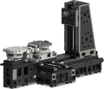
A casing is a box with bores on two or more faces, which is exactly the case a horizontal machining center with a rotary table is built for. The part is clamped once, the table indexes, and the bores and faces stay tied to each other through the table's position instead of through a fixture's repeatability. This is the machine that removes the concentricity problem at its source.
A lathe with live tooling for small impellers
A small impeller with a bore, a hub and straight vanes can be turned and milled in one clamping on a lathe with live tooling. The bore and the vane pattern come off the same clamping, so the imbalance from eccentricity is small before balancing starts.
A five-axis machine for closed impellers
Closed impellers with curved passages are five-axis work, or they are made in two pieces and welded. Where the shop does not have five-axis capacity, the design decision to split the impeller is what makes the part producible rather than the machine choice.
Process Notes for Pump Parts
Pressure-test the casing before finish boring
A casting that leaks will leak whether or not it is bored, and finding that out after the finish bore means scrapping a part with hours in it. Pressure testing after rough machining and before finish boring is the sequence that protects the investment.
Control the wear ring clearance by measurement, not by nominal
The clearance between the impeller wear ring and the casing ring is set by the two finished diameters, and it is small. Measuring both on the part, rather than trusting the boring bar's setting, is what keeps the clearance in the range the pump was designed for.
Deburr the volute and the passages
A burr left in a volute or a vane passage changes the flow and can break off into the pump. Deburring the internal passages, with a tool that can reach them, belongs in the process plan rather than in a hand operation after assembly.
Related Guides
- CNC machining pump parts - the full process route
- Bearing housing machining - the same bore-to-bore concentricity problem
- Hydraulic valve body machining - bores and seal faces in one body
- Horizontal machining centers - multi-face boring in one clamping
- CNC mill-turn machines - impeller work in one setup
More Application Guides
Handemo builds machines for each of these part families. Each guide covers what the part demands from the machine and how the process is sequenced.
Discuss Your Pump Components
Send the casing drawing with the bore tolerances and the wear ring clearance, the impeller type and material, and the batch size, and we will suggest the machine and the sequence.
Request a Process Review