
CNC Machines for Bearing Housing Machining
How bearing housings are machined: bore roundness after clamp release, coaxial bores across two walls, and choosing lathe, VMC or HMC for housing work.
Machining Bearing Housings
A bearing housing looks like a simple part until the bore is measured after the clamp is released. The bore that read round in the chuck or under the fixture comes back oval, or the bolt pattern no longer lines up with the mating face, and the housing that looked finished on the machine is scrap at assembly. Bearing housing machining is a datum problem and a clamping problem before it is a cutting problem, and the machine choice follows from getting those two right.
This page covers what decides whether a housing holds its bore, how to choose between a lathe, a vertical machine and a horizontal machine for housing work, and what to establish on the drawing before a fixture is designed.
Why Bearing Housings Move After Machining
The bore is round only while it is clamped
A housing with a thin wall under the bore is a spring. Chuck jaws or fixture clamps push the wall in while the tool cuts, and the wall comes back when the clamps open, so the bore that measured to size on the machine is oval once the part is free. The reading that matters is the one taken after release, and the only way to see how much the clamping is moving the wall is to measure in the clamp and again after release on the same part.
Two bores on two faces are a datum question
A single-bore flange housing is one operation from a machined face. A housing with a bore in each of two opposite walls is a different problem: the two bores have to be coaxial, and whether they are depends on whether both are cut in one setup with the part indexed, or in two setups with the part moved. The first holds alignment through the machine; the second holds it only as well as the fixture repeats, and on a split or two-wall housing that difference is usually the whole tolerance budget.
Casting skin and residual stress
A cast housing arrives with a hard skin, draft, and internal stress from cooling. Cutting the skin in one pass puts the tool under clean metal; skimming the high spots first work-hardens the cast surface and the finish pass then cuts damaged material. And a bore cut before the mounting face is milled will move when the face cut releases the casting, so the sequence matters as much as the machine.
Bolt patterns expose fixture error
A bolt hole drilled and tapped in the same setup as the face it belongs to will line up. The same hole put in during a second operation will not, because the re-clamp error moves it by a few hundredths that the bolt will not forgive. A housing that will not bolt to its mount is scrap regardless of how good the bore is, which is why the pattern is a test of the process, not a detail.
Lathe, Vertical or Horizontal
When the housing belongs on a lathe
A round housing, a flanged sleeve, or a bearing cartridge with a long bore and a machined outside diameter is a turning part. Bore and outside diameter come off the same axis in one clamping, so concentricity is held by the machine rather than by a fixture, and that is worth more than the higher metal removal a machining center offers. These parts run on a CNC slant bed lathe with a steady rest for the length, and on a mill-turn machine when the same part also needs cross ports or a flange pattern that would otherwise force a re-chuck.
When it belongs on a vertical machining center
A single-bore flange housing, a pillow block, or a housing that sits on a large mounting face is a vertical machine job. The part is clamped on the face or in soft jaws, the bore is interpolated or bored from above, and the mounting face, bolt circle and mounting feet are cut in the same setup. Support under the bore line matters more than table size here, because the wall deflects away from the tool and no amount of machine rigidity compensates for an unsupported wall.
When it belongs on a horizontal machining center
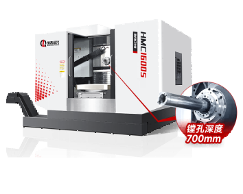
A split housing, a two-wall housing with coaxial bores, or a housing with machined faces on three sides is a horizontal machine job. The rotary table indexes each face to the spindle without releasing the part, so the bores and faces stay tied to one datum, and the setup count drops from three or four to one. Pallet changers and multi-station tombstones then let the machine run while the operator loads the next part, which is where housing work at volume actually pays.
What to Settle Before the Fixture
Which feature is the datum
On a housing the datum is rarely the outside of the casting. Castings are drafted, they are not square, and they vary from part to part, so using the outside as a reference is how the bolt pattern ends up where the mating part cannot reach. The datum has to be a machined face or a machined bore, and the first operation exists to create it.
The finished and blank drawings together
The finished drawing says what the part must be; the blank drawing says what there is to work with. Allowance per face, whether the casting is stress-relieved, and where the chucking or clamping points can be are all on the blank, and a process route designed from the finished drawing alone usually ends up asking for material that is not there or clamping where there is nothing to clamp.
Tolerance against process capability
A bore tolerance of a few hundredths on a 200 mm bore is routine; the same tolerance on a 500 mm bore with a thin wall is not, because thermal growth and clamp release both scale with size. Deciding which is the case before quoting is the difference between a job that ships and a job that is reworked twice.
Process Notes for Housing Work
Rough, then finish after the part settles
Roughing the bore and the faces, then finishing after the casting has been allowed to move, keeps the final geometry stable. Taking the finish cut immediately after roughing leaves the part to relax after it has been measured, and the bore that was in tolerance at inspection drifts out of it in the customer's hands.
Bore both walls from one direction where possible
Line boring from one end straight through both walls holds coaxiality better than boring each wall from its own side, because there is no datum transfer between the two. Where the bore is too long for one pass, boring from both ends with a bar sized for the depth rather than the diameter keeps the two halves aligned.
Measure the part the way the customer receives it
A housing is judged at assembly, with the bearing fitted and the bolts tightened. Measuring the bore free-standing and calling it good ignores the distortion the bolts introduce, so a check with the housing bolted to a plate is worth more than a more precise measurement of a free part.
Related Guides
- Bearing housing CNC milling: bore tolerance - the milling side of housing work in detail
- Vertical vs horizontal machining center - how many faces decide the architecture
- Slant bed CNC lathe explained - the turning route for round housings
- Box and housing parts - gearbox and pump casings with bores on several walls
More Application Guides
Handemo builds machines for each of these part families. Each guide covers what the part demands from the machine and how the process is sequenced.
Discuss Your Bearing Housing
Send the finished and blank drawings, the material, the bore tolerance and the batch size, and we will suggest the machine and the setup that holds it.
Request a Process Review