
CNC Machines for Sprocket and Gear Machining
Sprocket and gear machining: bore-to-pitch-circle runout, face squareness, thin disc clamping and keyway phase, plus hobbing versus interpolating.
Machining Sprockets and Gears
A sprocket or a gear is a part where the tolerance that matters is not on any single feature — it is the relationship between the bore, the pitch circle, and the face. A sprocket with a perfect tooth form on a bore that is 0.03 mm off centre will run tight on the chain at one point of every revolution, and the customer will hear it before he measures it.
This page covers how tooth and pocket geometry is cut, why the bore and the pitch circle have to come off the same datum, how to hold a thin disc without it springing, and what decides between a lathe with live tooling, a mill-turn machine and a machining center.
What Decides Whether a Sprocket Runs True
The bore is the datum, not the teeth
Tooth form is generated by the cutter and the index, and modern machines hold that easily. What is not automatic is where the tooth circle sits relative to the bore that the shaft goes through. If the bore is turned in one setup and the teeth cut in another, the offset between them is the fixture's repeatability plus the re-clamp error, and on a part that runs at speed that offset is what produces the vibration. Cutting the bore and the pitch circle from the same clamping removes the question.
Face runout shows up as chain wear
A sprocket that is square to its bore but not flat will pull the chain sideways once per revolution, and the wear shows up on the chain before it shows on the sprocket. The face that seats against the hub and the tooth plane have to be parallel within the drawing, and that parallelism is set by how the part is clamped, not by how flat the cutter is.
Thin discs spring under the jaws
A sprocket is usually a thin disc, and a thin disc in a three-jaw chuck is a spring. The jaws push the rim in while the bore is cut, and the bore comes back oval when the part is released — the same problem as a thin-wall housing, in a flatter geometry. Soft jaws bored to the part diameter, low clamp pressure, and a check after release are the fix.
Hardened parts move after heat treatment
A gear that is case-hardened or through-hardened after machining will distort in the furnace, and the bore is usually the feature that moves most. Either the finishing allowance is left for grinding after heat treatment, or the hardening process is chosen to limit distortion and the bore is finished before it. Deciding which before the process route is written avoids a batch of parts that cannot be corrected.
How the Teeth and Pockets Are Cut
Hobbing and shaping for involute gears
An involute gear tooth is generated by a hob or a shaper, and both are dedicated operations that run on a gear machine rather than a machining center. Where the shop has a gear machine, the machining center's job is to deliver a blank with the bore, faces and datum correct, so the gear machine has only the teeth to cut. Where it does not, the gear is bought in or the design is changed to a profile a milling machine can produce.
Milling and interpolating for sprocket profiles
A sprocket tooth is a profile, not an involute, and it can be milled with a form cutter or interpolated with an end mill on a three-axis machine. Interpolating is slower per tooth but needs no special cutter, and it holds the tooth-to-bore relationship in the same clamping as the bore — which is usually worth more than the cycle time on small and medium batches.
Pockets, lightening holes and keyways
Most sprockets carry lightening pockets, a keyway, or both. A keyway cut in a second operation drifts relative to the teeth by the re-clamp error, and on a part with a timing function that drift changes the phase of the drive. Cutting the keyway in the same clamping as the bore, or indexing from a machined feature rather than from the outside diameter, keeps the phase correct.
Which Machine for Which Part
A lathe with live tooling for small sprockets
A sprocket under roughly 300 mm that needs a bore, two faces, a keyway and lightening holes can be turned and milled in one clamping on a lathe with live tooling and a C or Y axis. The part never leaves the chuck, so the bore and the tooth circle stay tied together, and the cycle is short because the tool changes are between operations on the same part rather than between setups.
A mill-turn machine for larger or harder parts
Above that size, or where the tooth profile needs a large-diameter cutter, a mill-turn machine with a turning diameter large enough for the part gives both the turning and the milling capacity in one clamping. The deciding number is the largest diameter the part needs to swing, not the part's weight.
A machining center for plates and segments
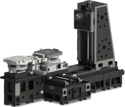
Large sprockets, ring gears and segments that are too big to swing on a lathe are machining center work: the part is clamped on a face plate or a tombstone, the bore is bored in place, and the teeth or pockets are indexed around it. On a horizontal machine with a rotary table the indexing is done by the table, which keeps the tooth spacing tied to the same datum as the bore.
Process Notes for Sprocket and Gear Work
Turn the bore and the seat face first
Everything else is located from the bore and the face that seats against the hub, so those two are cut first and in one clamping. Once they exist, the part can be held on them for the tooth and pocket work, and every later operation inherits a real datum rather than the outside of a sawn blank.
Check the tooth-to-bore runout, not just the tooth form
Tooth form is easy to inspect and easy to pass; the runout between the tooth circle and the bore is the number that decides whether the part runs quietly. Measuring it on a mandrel in the bore, with a dial indicator on the tooth tips, is the check that catches the error the customer will hear.
Deburr before heat treatment
A burr left on a tooth flank becomes a hard burr after hardening and a stress riser in service. Deburring belongs before the furnace, and on an interpolated tooth profile the deburring pass can often be part of the same toolpath.
Related Guides
- CNC machining sprockets - the full process route
- CNC machining gears - blank preparation and heat treatment
- Bearing housing machining - the same thin-wall clamping problem
- CNC slant bed lathes - turning with live tooling
- CNC mill-turn machines - one-setup sprocket work
More Application Guides
Handemo builds machines for each of these part families. Each guide covers what the part demands from the machine and how the process is sequenced.
Discuss Your Sprocket or Gear
Send the drawing, the tooth or profile specification, the bore tolerance, the material and whether the part is hardened after machining, and we will suggest the machine and the clamping.
Request a Process Review