CNC Machining Sprockets: Process and Machines
A sprocket looks like the simplest part in a drive train. It is a disc with teeth and a hole. Then the chain arrives, and the disc either runs quiet for two years or starts climbing the teeth after three weeks. Nothing in between. The difference is almost never the tooth shape the drawing calls out. It is the relationship between three things the drawing shows on three different views: the tooth circle, the bore, and the face the sprocket sits against.
We machine sprockets for conveyor builders, agricultural equipment makers and motorcycle aftermarket suppliers, and the same conversation happens in all three. The customer has a chain, a centre distance and a ratio. They need a sprocket that keeps the chain on. What they order is a turning job with a milling operation on the side. What they actually need is a part where the teeth and the bore agree, because the bore is what the shaft controls and the teeth are what the chain follows.
This article walks through that part: what the families are, which materials come through the door, how the sequence should be ordered, and where a vertical machining center earns its place instead of a hobbing machine.
What counts as a sprocket job
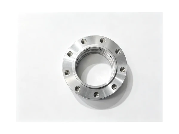
The word covers more ground than most buyers expect. A roller chain sprocket for a conveyor has a defined tooth form, a pitch circle and a fairly thin web. A double-pitch sprocket for a heavy conveyor looks like the same part with every other tooth removed, and runs at half the speed with twice the load per tooth. A taper-lock sprocket is a plain disc with a tapered bore and a keyway, and the bushing does the gripping. A split sprocket is two halves bolted together so the maintenance crew can change it without pulling the shaft.
Then there are the parts that get called sprockets but are not: timing belt pulleys, chain wheels on hoists, drive sprockets on agricultural feeders, and the cast iron wheels on older conveying lines. Each one shifts the work. A timing pulley wants a clean tooth flank and a flat face. A cast wheel may need the bore and both faces machined before the teeth can be cut at all, because the casting is not round enough to indicate from.
The families we see most often in a job shop are the plate sprocket, the hub sprocket and the taper-bore sprocket. All three start as a turning job and end as a milling or hobbing job, and the decision that matters is which end comes first.
Materials, and what each one does to the plan
Mild steel such as S275 or 1045 is the default for conveyor sprockets. It machines easily, welds if a hub has to be added, and can be induction hardened at the teeth afterwards if the duty cycle is heavy. The catch is distortion: a plate sprocket 12 mm thick will bow when it is case hardened, and a bowed sprocket runs on one side of the tooth. Shops that harden after machining usually leave the bore undersize and finish it after heat treatment, which means the bore is cut in a second operation on a machine that can hold the part by the teeth.
Stainless grades such as 304 and 316 come through for food conveyors and washdown lines. They machine with more heat at the edge, they work harden if the tool rubs, and the tooth flanks tend to smear if the feed is too light. A stainless sprocket is also more likely to be laser cut as a blank and then only machined at the bore and faces, because the tooth profile is not load bearing in the same way on a low-speed food line.
Hardened and wear-resistant steels appear on mining and heavy conveyor drives. Machining is done in the annealed state and the teeth are cut before hardening, or the part is bought as a flame-cut blank in a wear plate grade and only the bore and keyway are machined. Aluminium shows up on light timing drives and on prototype fixtures, where the part is a fraction of the weight and the machine can run at higher spindle speed without fighting chatter.
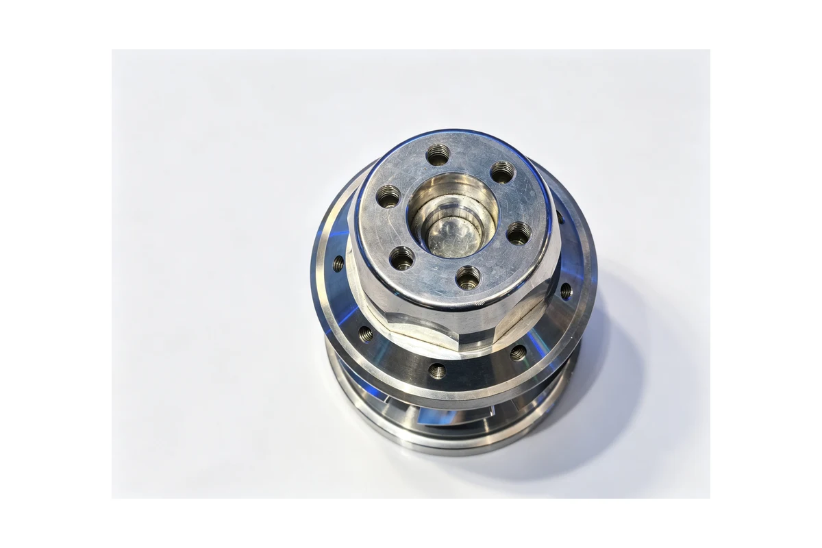
Cast iron sprockets are still common on older equipment. The casting has draft on the faces, a skin that will dull a cutter in the first pass, and enough variation that the first operation is usually to face both sides and establish a bore, not to cut teeth. Only after that does the tooth circle have something to be concentric with.
Why the sequence decides the result
Most sprocket problems that reach us as complaints are sequence problems. The drawing shows a pitch circle, a bore with a keyway, two faces and a set of bolt holes. A shop that turns the blank, cuts the teeth on a hobbing machine, then drills the bolt holes from the outside will usually get a part that runs, but the bolt holes will be clocked off the teeth by whatever the chuck happened to do. On a split sprocket or a two-piece drive that matters, because the joint has to land between teeth, not on one.
The other common route is to cut the teeth first on a laser or waterjet, then turn the bore. That route is fast and it is fine for low-speed conveyors, but the tooth flanks come off the cutter with a heat-affected edge, and turning afterwards cannot fix a pitch circle that was cut oval.
The route that holds up is the one where the bore, the face and the tooth circle are established in the same clamping, or where the tooth circle is cut from the bore as its datum. That is a machine choice, not a tooling trick: you need a machine that can hold the blank by the outside diameter, face it, bore it, and then mill or interpolate the tooth profile without the part changing hands.
Where a vertical machining center fits
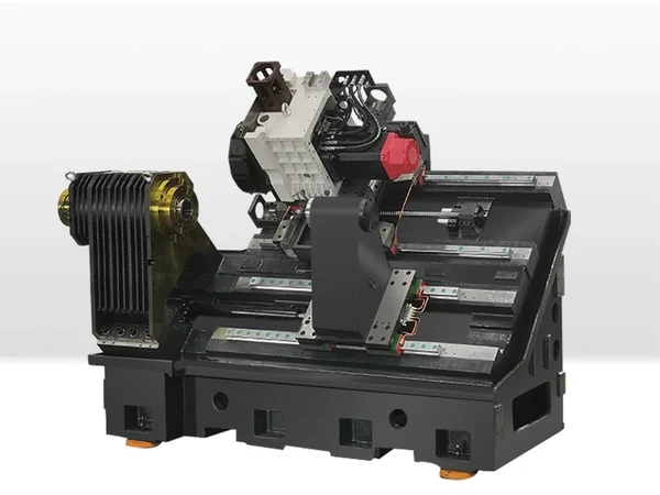
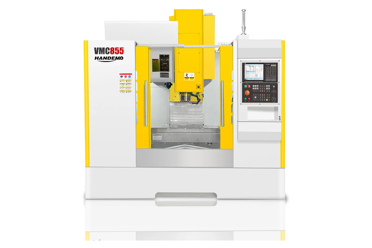
For sprockets up to roughly 500 mm outside diameter, a VMC855 covers the whole part in two setups. The table is 1000 x 550 mm with a 600 kg rating, travels are 800 / 550 / 550 mm, and the BT40 spindle runs to 8,000 rpm. That envelope holds a 400 mm sprocket with a hub on a fixture plate and still leaves room for the boring head.
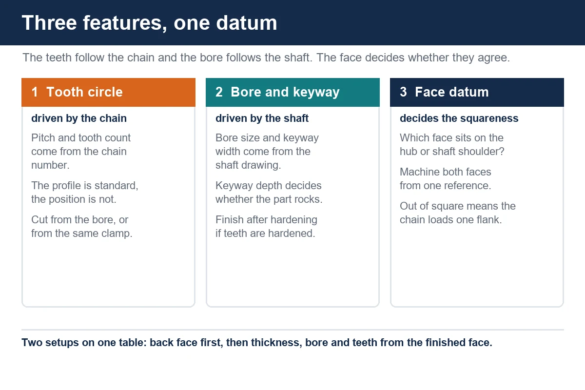
The first setup is the back face: clamp on the rough outside diameter, face the back, bore the pilot, and put in the bolt circle if the part has one. The second setup clamps on the finished back face and the bore, faces to thickness, finishes the bore and keyway, and interpolates the tooth profile. Both the bore and the teeth come off the same datum, so the runout between them is whatever the machine and fixture allow, not whatever the chuck happened to do.
For larger conveyor and agricultural sprockets, the VMC1160 opens the envelope to a 1200 x 600 mm table rated at 800 kg, with 1100 / 600 / 600 mm travels and the same BT40 8,000 rpm spindle. A 600 mm sprocket with a welded hub is a normal job on that table, and a plate sprocket can be clamped flat with the full face supported instead of overhanging the edge.
What a VMC does not do as fast as a hobbing machine is cut a long run of identical teeth. Hobbing wins on volume, because the cutter engages continuously. A VMC wins on the mixed shop: one off, five off, a part with a bore and a keyway and a bolt pattern that all have to agree, and a delivery date that does not allow waiting for a hobbing slot. For anything under a few hundred pieces a year, the setup time on the VMC is usually the smaller number.
The operations that cause trouble
The keyway. A keyway is a single cut that has to be on centre and parallel to the bore axis, and it is the feature most often cut last with the part held in a vice. Broaching is faster on a long run, but on a mixed shop the keyway is usually milled with a slot drill or a small end mill, one pass, then checked against a gauge key. The risk is not the width, it is the depth: cut too deep and the key rocks, cut too shallow and the key will not seat, and both show up as a sprocket that walks on the shaft.
The web and the lightening holes. Large sprockets are often turned with a web and a set of lightening holes to cut rotating mass. Those holes are a machining decision, not a drawing formality: drill them after the bore is established, from the same datum, or the balance will be off and the chain will see it as a once-per-revolution pulse. On a sprocket running at several hundred rpm, an unbalanced web is audible before it is measurable.
The tooth profile. Roller chain tooth forms are defined by the chain standard, and the profile is normally generated with a form cutter or interpolated with a small end mill on a rotary or a CAM path. The practical issue is chip evacuation at the root: a deep, narrow root on a hard material will pack chips and break a small cutter, so the roughing pass should clear the root before the finishing pass touches the flank.
Hardened teeth. If the teeth are induction hardened after machining, the bore and the keyway are usually finished afterwards, because the hardening pulls the part. That means the part comes back to the machine held by the hardened teeth, and the fixture has to be soft enough not to mark them. A set of soft jaws bored to the tooth outside diameter is the usual answer.
Holding consistency across a batch
A conveyor line does not care about one sprocket. It cares that the replacement fits the shaft, aligns with the drive sprocket, and does not change the chain tension. That is a consistency question, and it is answered before the first cut: the same fixture, the same datum, the same probe routine on every part, and a first-off check that records the bore, the face squareness and the tooth clocking.
On a batch of fifty sprockets, the variable that drifts is not the machine. It is the fixture. Soft jaws bored for one diameter get re-bored for the next size and lose their concentricity, and a vise that is cleaned once a shift will hold a part differently at 10 am and 4 pm. The shops that hold a batch together are the ones that treat the fixture as a part number and keep it with the job.
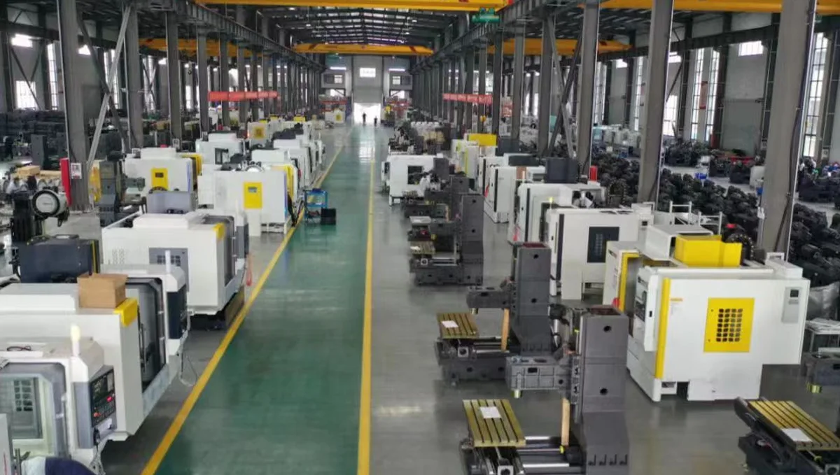
We build our vertical machining centers around that reality: a rigid frame, box or linear guideways chosen for the duty, and a table sized so the part sits supported rather than cantilevered. The gear machining guide covers the same family of problems from the toothed-part side, and the machining solutions section has the rest of the part types we write about.
What to put on the enquiry
Most sprocket enquiries arrive as a chain number and a tooth count. That is a good start and it is not enough. What changes the quote is the outside diameter, the bore and keyway size, the face thickness, whether the part is a plate or has a hub, the material and its condition, the batch size, and whether the teeth are hardened after machining.
If the drawing shows a pitch circle and a bore but no datum, say which face sits against the mating part. That single piece of information decides the setup order and often removes an operation. If the sprocket replaces an existing part, the failed part is more useful than the drawing, because the wear pattern on the teeth and the shaft tells us whether the problem was the profile, the bore or the face.
Questions we get
Can a sprocket be cut entirely on a machining center?
Yes, up to the table and travel limits of the machine. Turning the blank, boring, keyway and interpolating the tooth profile can all happen on a VMC with a rotary table or a fourth axis. For long production runs a hobbing machine is faster on the teeth, but the bore and faces still come off a lathe or a mill first.
Should the teeth be cut before or after hardening?
Cut before, then finish the bore and keyway after. Hardening moves the part, and a bore finished before hardening will not be round enough to sit on a shaft without a fight. If the tooth profile itself is hardened, the finishing pass on the flanks happens before the heat treatment and the part is not touched at the teeth afterwards.
How do I stop a sprocket from wearing on one side?
Check the face that sits against the hub or the shaft shoulder, and check that the bore is square to it. A sprocket that is out of square runs tilted, the chain loads one flank, and the wear pattern appears on one side of every tooth. The tooth profile is rarely the cause on a part that ran correctly for a while.
What batch size makes a dedicated fixture worthwhile?
Around twenty pieces. Below that, soft jaws and a probe routine are cheaper than a dedicated plate. Above that, a fixture that locates on the bore and the back face pays for itself in setup time alone, before any gain in consistency.
Do you machine split sprockets?
Yes. The two halves are machined as a pair, bolted together on a fixture, with the joint line marked before the teeth are interpolated. The joint has to fall between teeth, so the fixture is built to hold the pair in the orientation they will run.
Next step
Send the drawing, the chain number and the batch size, and tell us which face sits against the mating part. We will come back with the setup plan, the machine, and a price that includes the fixture if the batch justifies one.
Contact Handemo CNC | Email: sales1@handemocnc.com | WhatsApp: +86 135 6320 3038