CNC Machining Gears: Process and Machines
Gears are the parts that make a machine shop ask the awkward question first: do we actually machine this, or do we buy it in? The honest answer is that most shops machine everything around the gear teeth, and the teeth themselves only come to the CNC when the volume is low or the geometry is awkward. That boundary is what this article is about.
It belongs to our machining solutions series, where each article takes one part family and walks through the blank, the materials, the setups and the machine that suits it. A gear is a good example because so much of what a buyer receives as a "gear" is really a turned blank with a few milled features on it.
What arrives as a gear job
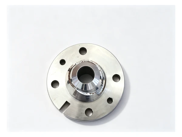
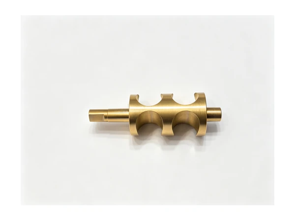
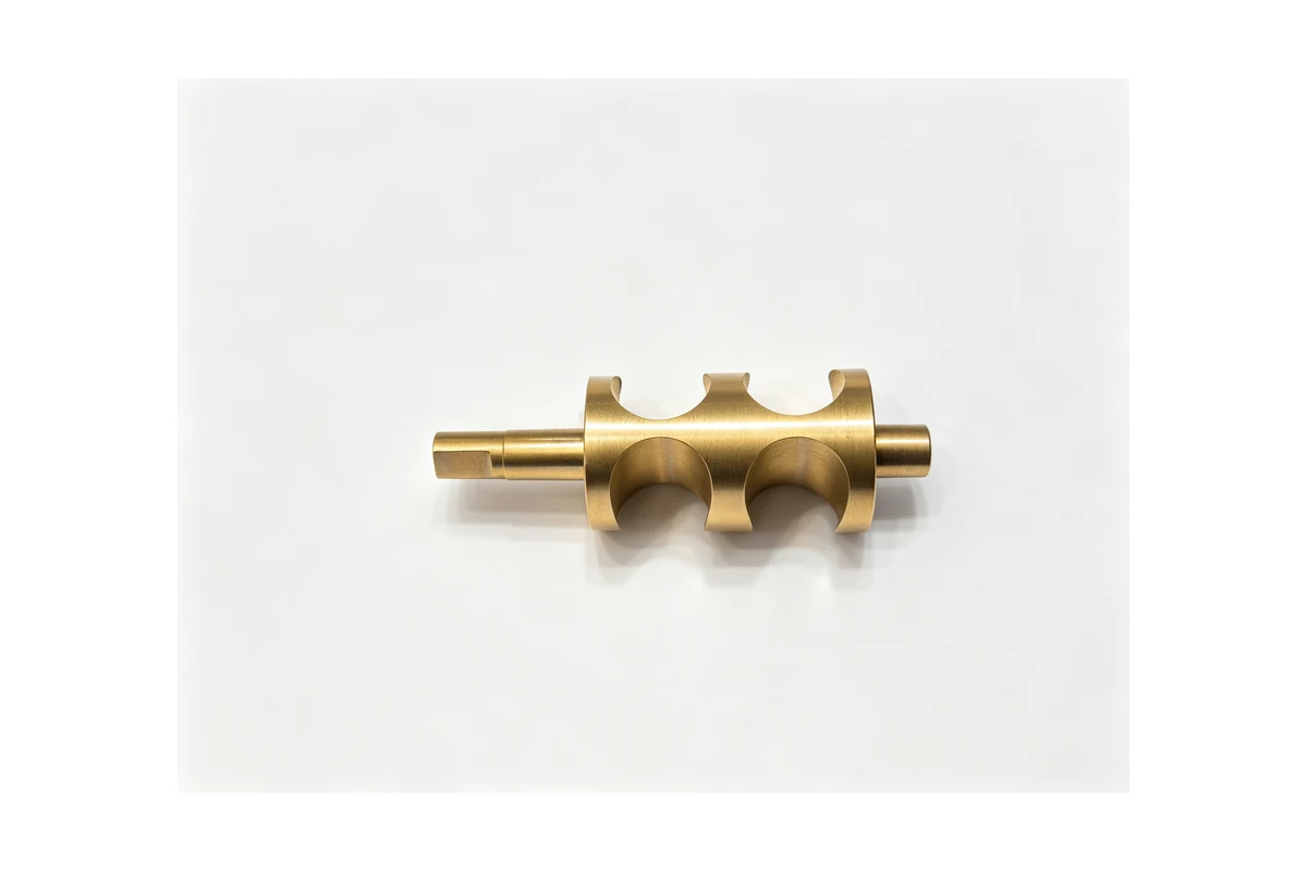
When a customer sends a "gear", it is usually one of four things. A blank, meaning a disc or a shaft that still needs teeth and the bore finished. A gear shaft, where the gear form sits on the same body as the journals and the coupling end. A worm or a worm wheel, which is a helical form on a shaft or a bronze rim. Or a gear-adjacent part such as a gearbox flange, an end cover or a bearing carrier that has to agree with the gear centre distance.
Only the first and the third categories really need the tooth form cut in-house for low and medium volume. Everything else is turning, boring, milling and keyway work that any competent shop should handle without drama.
Materials that come through the door
The common gear steels are case-hardening grades such as 20CrMnTi and 17CrNiMo6, through-hardening grades such as 42CrMo4 and 40Cr, and plain carbon steel for lower-duty parts. Worm wheels are usually bronze or a bronze rim on a steel hub. Cast iron appears on large, slow gears and on the housings that carry them, and stainless shows up wherever the gear runs wet or in a food environment.
The material decides how the blank behaves. A case-hardening steel machines soft, then distorts in heat treatment, so the shop has to leave something to grind after hardening. A through-hardening steel is tough to turn in the hardened state, so the sequence changes. The point is that CNC work on gears is planned backwards from the heat treatment, not forwards from the drawing.
Turning the blank
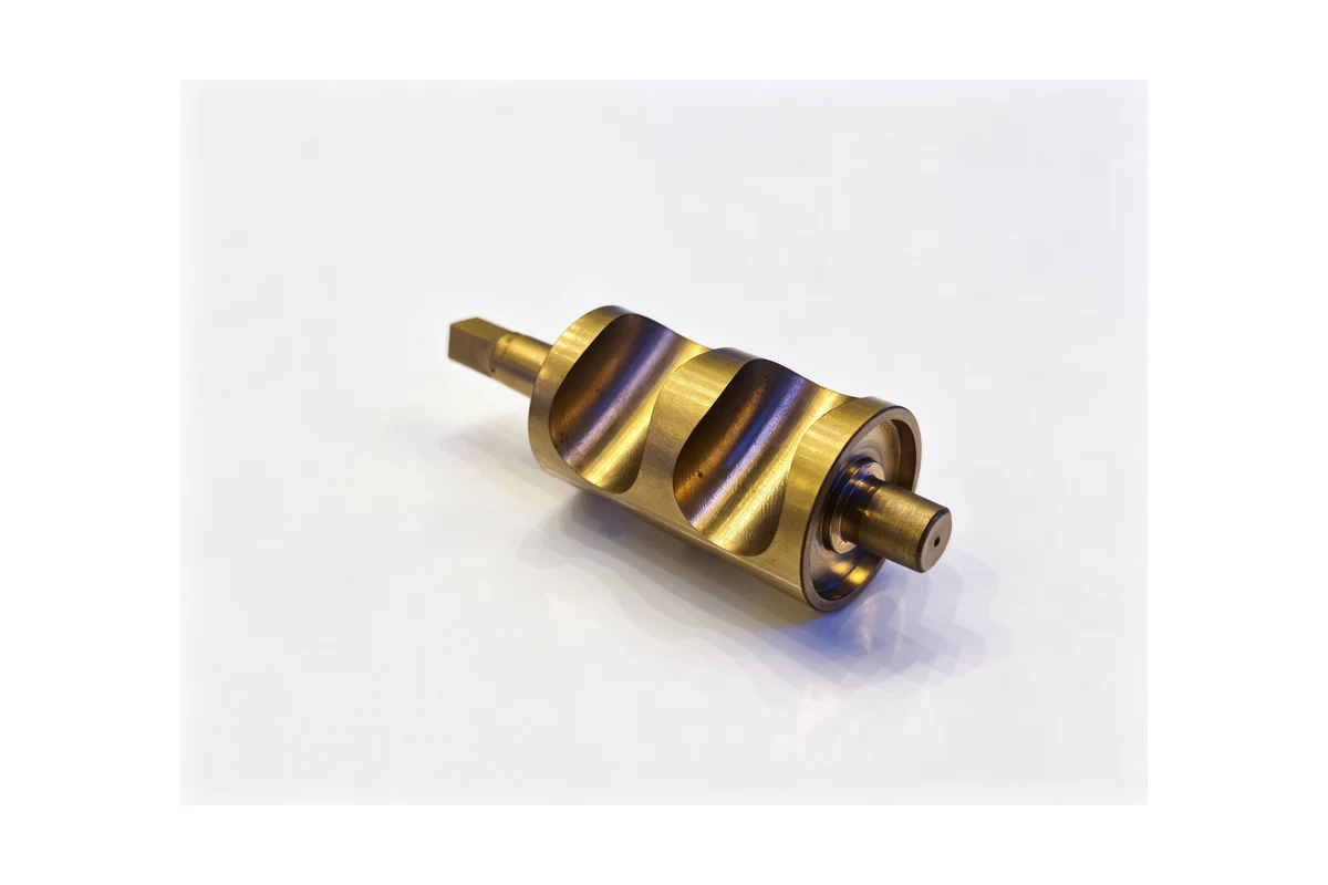
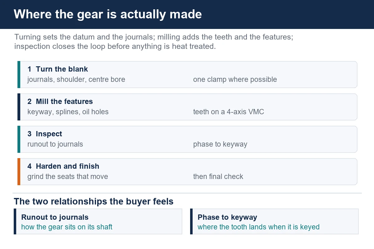
The first operation on almost every gear is turning, and it is where the part is either set up for success or ruined. The blank is turned between centres or on a mandrel, with the two bearing journals, the shoulder faces and the reference bore all produced in one clamp wherever the part allows it. Runout between the journals and the gear seat is what the assembly feels later, and it is easiest to control when those features come off the same machine without a re-clamp.
For this work a slant bed lathe such as the TCK50 handles everything up to the medium gear sizes comfortably, including a boring bar pass through the centre and a grooving cycle for the retaining shoulder. When the part has a long shaft on both sides of the gear, a mill-turn machine takes the second end without turning the part around.
Cutting the features on the gear body
Once the blank is round and true, the features go on a vertical machining center with a fourth axis or an indexing fixture. Splines, keyways, oil holes, tapped clamping holes and the tooth form itself for low-volume gears are all work a four-axis VMC can do, and a model such as the VMC855 with a rotary table covers a wide range of gear diameters without a special machine.
For a helical form, the rotary axis is interpolated with the linear axes while the cutter follows the helix angle. That is a legitimate way to make a small batch of gears, and it is the same technique used for helical splines and for the leads on a worm. For high-volume gears with a defined rating, hobbing and grinding still win on cost per piece, and a responsible shop will say so.
When the gear sits in a housing
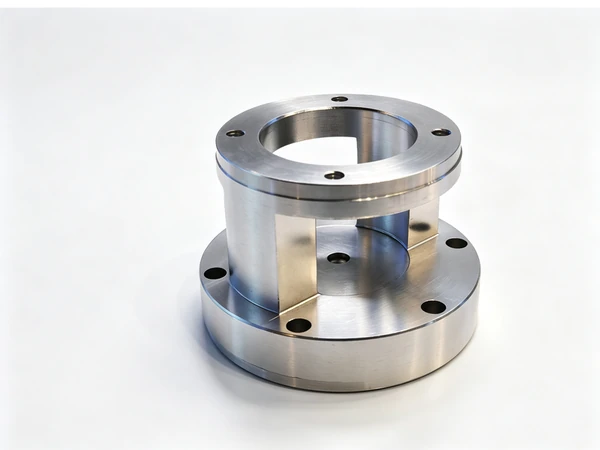
Gearboxes and gear drive assemblies bring a second family of parts: bearing carriers, end covers, flanges and the housing itself. These are multi-face jobs with bores at right angles and centre distances that have to be held between them. That is horizontal machining center territory, because the part is held once and the table indexes instead of the operator re-clamping. Our HMC630-DT runs this kind of work, and the same setup logic is described in the pump casing case study on the blog.
If the gears and the housing come from the same supplier, the shop controls the centre distance from blank to finished assembly instead of discovering it at the customer's press.
Workholding and clamping
Gear work is unforgiving about clamping. A disc held in three jaws will go out of round if the jaws are too tight, and the distortion disappears when the part is released, which is exactly when nobody is measuring. What works for this family in practice:
- Turn the first side on a face driver or between centres, then grip on a finished bore with a mandrel for the second side.
- Keep clamp pressure consistent between parts, and record it, so the second half of the batch matches the first.
- Support thin gear rims from underneath during any interrupted cut, because a rim that flexes during a keyway cut will not run true afterwards.
- Cut the keyway and the splines in the same clamp as the tooth form when the geometry allows, so the phase between them is set once.
- Use through-tool coolant on deep bores and blind pockets, and program the exits so chips leave the tooth spaces.
Inspection and what the buyer should ask for
No gear is bought on the drawing alone. The relationships that matter at assembly are the runout of the gear body to the mounting journals, the phase between the tooth form and any keyway or spline, and the centre distance when the gear pairs with a mating part. A shop that machines gears should be able to show the inspection record for those on each batch, not just the bore size.
We do not publish machine accuracy figures or tooling data for export control reasons, so this article stays with the process rather than the numbers. If you need the specifics for your part, send the drawing and we will quote the process.
FAQ
Can you cut gear teeth on a CNC mill?
Yes, for low and medium volume on a four-axis or five-axis machine. The rotary axis is interpolated with the linear axes so the cutter follows the helix or the tooth form. At high volume a hobbing machine is cheaper per piece, and we will tell you when that is the case.
Do you machine the gear blank as well as the teeth?
Both. Turning the blank, boring the centre, cutting the keyway and the splines, and milling the tooth form for a small batch all happen here, which keeps the datum chain short.
What do you need to quote a gear job?
The drawing, the material and the heat-treatment callout, the batch size, and the mating part if the centre distance matters. If the gear pairs with something you already have, send that too.
Do you handle heat treatment?
The machining sequence is planned around it, and the finishing operations that follow hardening are part of the quote run in-house. Tell us the hardness callout and the process follows from there.
Contact Handemo CNC | Email: sales1@handemocnc.com | WhatsApp: +86 135 6320 3038