Forged Blank Machining: Why You Cannot Dial In the Die
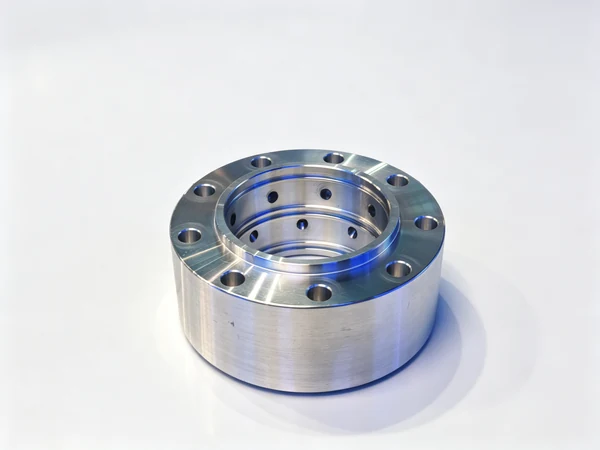
The call came from a shop that turns forged flanges for hydraulic cylinder ends. They had run the same family of parts for years, first from saw-cut bar, then from closed-die forgings once the volume justified the tooling. The bar parts had been easy. The forged parts were not, and the reason took them three weeks and one scrapped batch to find.
What they were doing was this. The blank arrived with a black, slightly lumpy skin and a raised line around its middle where the two halves of the die had met. The man on the lathe set the part in the chuck, put a dial indicator on the outside of the black skin, tapped it until the needle sat still, and cut. The outside cleaned up. The face cleaned up. The bore, cut in the same setup, came out true to the outside.
And that was the problem. The outside was true to the die. The bore was true to the outside. So the bore was true to the die, and the die is not the drawing.
This is one of our machining solution notes, written from what shops send us. It is about forged blanks: what the black skin actually is, why splitting the stock evenly is not possible on a forging, and the order of operations that makes the problem go away. If you machine castings rather than forgings, most of it still applies, because a casting carries the mould's shape for the same reason.
What a Forged Blank Actually Is
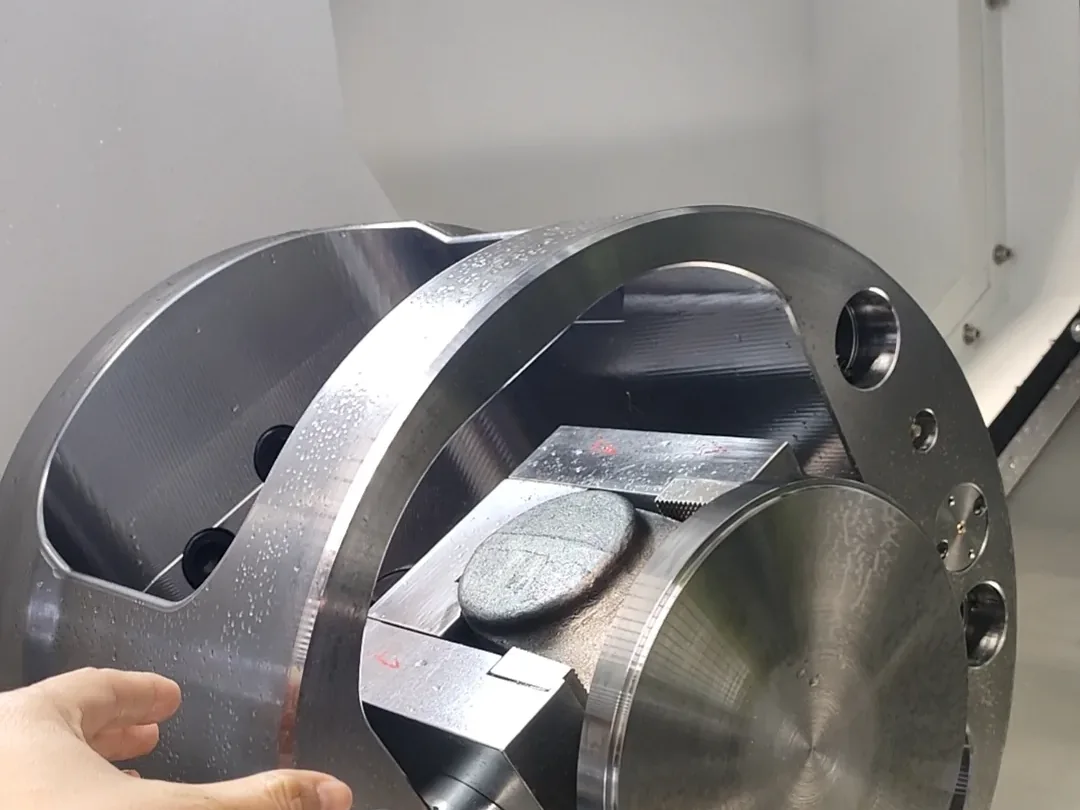
A closed-die forging starts as a cut length of bar that is heated and then squeezed between two shaped dies. The metal fills the die cavity, and whatever does not fit escapes as a thin fin of flash around the parting line. The flash is trimmed off, and what is left is a part that is close to the final shape but is not the final shape.
Three things about that process end up on your machine table.
The first is draft. A die cannot have vertical walls, because the part would not come out. Every surface that runs in the direction of the press has a small taper, typically a degree or two. On the drawing of the finished part that surface is a cylinder or a flat. On the blank it is a cone. It looks flat, it measures flat across a short distance, and it is not flat.
The second is the parting line. This is the one feature on a forging that means something, and what it means is orientation. It tells you where the two die halves met, which tells you which way the metal flowed, which tells you where the flash land was and where the die wore. It does not tell you where the centre of the part is.
The third is scale. Hot steel in air grows an oxide layer, and that layer is not a coating you can wipe off. It is a different material, harder and more abrasive than the metal underneath, and it does not sit at a constant thickness. Where the die was hottest and the metal moved most, the scale is thicker and rougher.
The material in this case was a 42CrMo4-type steel, the chromium-molybdenum grade that most European drawings call out for a flange or a hub that has to carry load. The Chinese equivalent, 42CrMo, behaves the same way. On the aluminium side the same conversation happens with 6082 or 6061 forgings, where the skin is an oxide film and a forge-lubricant residue rather than mill scale, but the shape problem is identical.
The Blank Carries the Die, Not the Part
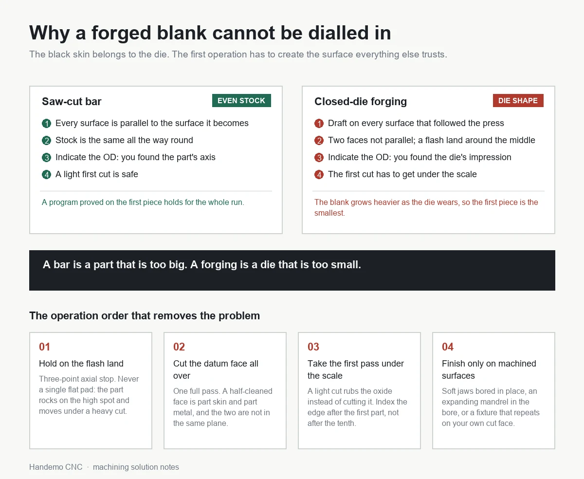
This is the sentence the whole article hangs on. A saw-cut bar is a cylinder that is simply too big: every surface is parallel to the surface it will become, and the stock is the same all the way round. A forging is not an oversized part. It is the die, pressed into steel.
Which means the surfaces you can touch on a blank are surfaces the die decided. The outside diameter has draft on it. The two side faces are not parallel to each other, because the two die halves did not close to the same depth on every part. The corners are die radii, not drawing radii, and they are generous because a sharp corner in a die is a crack waiting to happen.
A bar is a part that is too big. A forging is a die that is too small.
Once you accept that, the failure mode of the shop above stops being a mystery. They indicated the black skin of the outside diameter. The needle went still, which felt like success. But a dial indicator on a draft-angled, die-worn surface is not finding the part's axis. It is finding the best circle that fits the die's impression. The part was then cut concentric to that circle, and every dimension that came off it was correct with respect to a shape that does not appear anywhere on the drawing.
The tell was in assembly, not in inspection. The flange bolted up fine on some parts and sat at a slight angle on others, because the bolt circle had been cut concentric to a different centre than the spigot on the back. Both dimensions met the drawing. They met it against two different axes.
If you want the machined-part version of the same idea, it is the reason a large flange that springs back has to be measured as a ring rather than as a diameter. In both cases the number on the drawing describes a relationship, and a single reading cannot see a relationship.
Why You Cannot Split the Stock Evenly
The instinct, when a blank is not symmetric, is to put half the extra material on each side. It is a good instinct and it works on bar. On a forging it is not available, and it is worth being clear about why, because shops keep trying.
To split stock evenly you need two surfaces that are each parallel to the surface they will become, and you need to know how far apart they are. On a forging, neither half of that is true. The outside is drafted, so the stock varies continuously around and along it. The two faces are not parallel, so putting the part between centres gives you an axis that is square to neither. And the die wears across a production run, so the amount of material in the flash region grows from the first parts to the last.
Die wear is the part that surprises people. A forging die is not a permanent thing. The flash land, the radii and the deepest corners all wear, and as they wear the cavity holds more metal. The blank gets heavier, not lighter, as the run goes on. The first fifty parts off a new die and the last fifty off the same die are the same drawing and not the same blank.
The practical consequence is that a program proven on the first piece of a run is not proven. The first piece is the smallest blank you will see. Prove the program on a part from the middle of the run, and check the stock on the last third, where the blank is at its largest and the faces are furthest apart. A shop that programs off the first article will find, three weeks later, that the back face has stopped cleaning up.
The First Operation Does Not Use a Datum. It Makes One.
Every process plan has a first operation, and on a machined-from-bar part that operation is usually described as "hold in chuck, face, turn". On a forging the same words hide a different job. The first operation is not allowed to trust anything on the blank, so it has to create the surface that everything afterwards will trust.
What that looks like in practice, on a lathe:
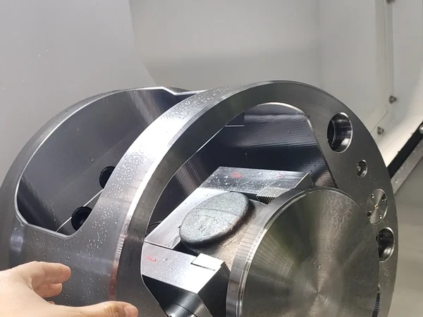
Hold the blank on the flash land or on the as-forged face near the parting line, with an axial stop that touches three points rather than one flat. Three points is the important part. A single flat stop on a forged face touches the high spot and leaves the part rocking on it, and a part that rocks under clamping pressure will be cut in one position and spring to another when the jaws open.
Then cut the face that is going to be the datum. Cut it all over, in one pass if the stock allows, and do not stop halfway to measure whether it is cleaning up. A half-cleaned face is the worst possible datum, because it is part machined surface and part black skin, and the two do not sit in the same plane.
From that point on nothing changes. The second operation holds the part on the face you just cut, and every dimension after that is measured from a surface that came off your own machine. The forging's job was to deliver material. It was never asked to deliver a reference.
Why three points and not a flat pad
Rough forged and cast surfaces are not flat at the scale a fixture cares about. Put one on a flat pad and it touches at three random high points, and the part stands on those three points like a stool with uneven legs. It will hold still under a light cut and move under a heavy one. Three adjustable pads let you seat the part deliberately instead of hoping. This is the same reason a rough casting is often set on a three-point rest and shimmed rather than dropped onto a face plate.
The First Cut Has to Get Under the Scale
Scale is not dirt. It is oxide, it is harder than the metal beneath it, and it is abrasive in a way that carbide notices. The mistake shops make on the first pass is to take a light cut, because the blank is not symmetric and they want to see where the material is before committing.
A light cut on a scaled surface does not cut the scale. It rubs it. The insert spends the pass in contact with a hard, broken, intermittently conductive layer, and the edge that comes out the other side is not the edge that went in. What follows is a dull tool trying to take the real cut, and the failure shows up as a notch on the flank or a chipped corner, which then gets blamed on the material.
The rule is simple: on a scaled or sand-cast surface, the first pass should be deep enough to be entirely inside clean metal. If the stock will not allow that, take the pass in a way that the entry is at an edge rather than in the middle of a skin, and expect to change the edge after the first part. Roughing a forging is not the place to be economical with inserts.
The same pass is also an interrupted cut in most cases. Forged blanks often have a parting-line ridge, a trimmed flash remnant or a step from die mismatch, and the tool goes in and out of material at every revolution. That is a different load case from a smooth bar, and it is the load case that decides whether the machine is heavy enough. This is why the answer to "can my lathe turn forged blanks" is mostly about mass and the spindle, not about the control.
Never Clamp the Finish on Black Skin
There is a version of this mistake that survives longer than the others because it sometimes works. It is: hold the rough blank in hard jaws, cut everything you can reach, then flip it and hold it on the black skin of the outside diameter to finish the second side.
It works on parts where the second side is loose on the drawing, and it fails on the parts that matter. A three-jaw chuck closing on a drafted, scaled, slightly oval surface makes contact at three lines, not three areas. Under cutting load, the part can rotate or creep in those contacts by an amount that is small in absolute terms and large compared with what the second side needs. You will not see it in the first part, because the operator tightened it well. You will see it in the part that was loaded slightly differently at two in the morning.
The fix is not a better chuck. It is to give the second operation a machined surface to hold, which means the first operation has to produce one. On a hub or a flange that usually means machining the bore and one face in the first setup and using a expanding mandrel or soft jaws bored to that bore for the second. On parts where neither side can be sacrificed, the answer is a fixture that locates on the as-forged parting line for the roughing operation only, and never appears again.
Normalising Sits Between the Two Operations
A forging is not in a neutral state when it arrives. It has been heated, squeezed and cooled, and the cooling was not uniform because the sections are not uniform. The result is a part with locked-in stress that is roughly shaped like the forging and will move when you cut it.
The sequence that shops settle on, for anything with a real wall thickness, is to rough, then stress-relieve or normalise, then finish. The roughing removes the scale and the bulk of the uneven stock, which is what makes the heat treatment effective; the heat treatment releases the stress that the forging brought with it plus the stress that the roughing added; the finishing cuts the shape that survives.
Skip the middle step and the parts will be right when they leave the machine and wrong a week later. Nothing about that is visible in the shop, which is why it usually gets discovered at the customer's assembly line, and why the argument afterwards is about who measured it wrong rather than about the sequence.
A forging is a shape with an opinion about its own dimensions. Heat treatment is how you get it to change its mind before you cut.
Which Machine, and Why Not the Smallest One That Fits
The question we get most often about forged work is whether a general-purpose lathe can do it. It can, up to a point, and the point is reached earlier than the envelope suggests. A blank that fits inside the swing is not the same as a blank the machine enjoys cutting, because the first roughing pass on a scaled forging is a heavy, interrupted cut taken at whatever depth the stock forces on you.
The table below is the range we build that covers this work, and the last column is the honest reason to pick one over another, not a restatement of the numbers.
| Machine | Working envelope | Why this one for forged blanks |
|---|---|---|
| TCK6350B | 630 mm swing over bed, 480–500 mm cutting diameter, 500 mm cutting length, 96 mm spindle bore, 85 mm bar capacity, 18.5 kW, 12-station servo turret, 4300 kg | The volume workhorse for forged hubs and flanges. The 18.5 kW spindle and the mass behind it are what let you take the first pass deep enough to clear scale instead of rubbing it, and the 96 mm bore means a forged ring can be held on a mandrel rather than in jaws. |
| TCK80-1500 | 1000 mm swing over bed, 800 mm cutting diameter, 1500 mm cutting length, 120 mm spindle bore, 105 mm bar capacity, 22 kW, 12-station servo turret, 12000 kg | For the parts that made someone ask the question. Twelve tonnes of machine is not about the envelope, it is about the interrupted cut and the part that is not round yet. Long forged shafts and large flanges with a hub on one end also need the 1500 mm cutting length. |
| TCK6050 | 560 mm swing, 500 mm cutting diameter, 550 mm cutting length, 65 mm spindle bore, 50 mm bar capacity, 11 kW with a 15 kW option, 12-station servo turret | The right answer when the forged family is small and mixed with bar work. Specify the 15 kW option if the same machine will rough forgings, and do not expect it to enjoy a 30 kg blank with a parting-line ridge on it. |
| VMC1690 | 1600 × 800 mm table, 1600/900/700 mm travels, 1500 kg table load, BT50 spindle | For the milling half of a forged part — pads, ears, bolt faces on a forged bracket or a forged steering component. BT50 and the table load are the two numbers that matter, because a forged bracket is heavier than the machined part and has to be clamped while it is still ugly. |
| HMC630II-ZT | Multi-station horizontal machining centre with a twin-pallet arrangement | When a forged housing has four or five faces that all need work, the horizontal keeps the part on one pallet and brings the faces to it. Fewer setups on a forging is worth more than on a bar part, because every setup is another chance to reference the die instead of the part. |
Two boundaries worth stating plainly, because they come up in every quote. First, none of these are forging presses or forge-shop machines. A machine that sits next to the press and cuts a blank while it is still warm is a different machine with a different spindle, different guarding and a different coolant strategy, and we do not build it. Second, a bigger machine does not fix a process that is referencing the wrong surface. If the plan still dials in on black skin, a twelve-tonne lathe will produce the same wrong part more slowly.
Castings Behave the Same Way, for a Different Reason
Shops that work in both forged and cast blanks tend to treat them as two problems. They are one problem with two mechanisms. A casting carries the mould's shape, including draft, a parting line, and a mismatch between the cope and the drag halves that appears whenever the boxes are not perfectly aligned. A forging carries the die's shape, with the same list.
The difference is in the surface. A casting arrives with sand, and sand is worse for the tool than scale because it is not attached to anything and it gets into everything — the coolant, the way covers, the chuck. A forging arrives with scale that is bonded and abrasive. Either way the first pass has to get under it, and either way you cannot dial in on it.
The other thing both have in common is that the blank's weight tells you nothing about the part's weight. A near-net-shape blank is designed to be close, not to be even, and the stock is distributed where the forging or casting process needed it. You will find parts with plenty of stock on the face and almost none on a boss, and no amount of indicating will put material back where the die did not.
What to Send Us With a Forged Part Enquiry
Most of the difficulty in quoting forged work is not the drawing, it is the blank. Four things settle it faster than a drawing package does.
Send the blank drawing, not only the finished one. The finished drawing tells us what the part is; the blank drawing tells us how much material you are asking a machine to remove and where it is. If there is no blank drawing, send the forging weight and the finished weight, and we can work out the ratio.
Tell us where the parting line is relative to the surfaces that matter. A parting line that runs across a sealing face is a different problem from one that runs around a diameter, and it changes which surface we would use to hold the part in the first operation.
Say whether the blank is normalised on arrival or whether you expect to stress-relieve between roughing and finishing. This is the single biggest difference between a two-operation plan and a three-operation plan, and it changes the machine recommendation more than the part size does.
And tell us what the part does when it is assembled. The shop in this article would have saved three weeks by saying "the flange sits at an angle on some of them" at the start, because that sentence describes a relationship between two features and points straight at the datum.
Questions We Get About Forged Blanks
Can a forging be machined without a datum?
Yes, and that is how it is normally done. The first operation does not use a datum from the blank; it holds the blank on the flash land or a rough face, and it cuts the surface that becomes the datum for everything after. What you cannot do is indicate the black skin and treat that as a datum, because the skin belongs to the die.
Why does my bore come out eccentric to the outside diameter?
Usually because one of the two was cut relative to the die rather than to the other. If the outside was dialled in on black skin, the outside is true to the die's impression, and a bore cut in the same setup is true to that. Check both diameters against a common machined face and see which one moves.
Should I rough before or after normalising?
Rough first, then normalise, then finish. Roughing removes the uneven stock and the scale, which is what lets the heat treatment actually relieve the part rather than just heat it. Finishing before normalising produces parts that are correct on the machine and move afterwards.
Why does the insert break on the first pass and not later?
Because the first pass is the only one that meets the scale and the parting-line ridge. A light first cut rubs the scale instead of cutting under it, and the edge that survives that is not sharp enough for the rest of the part. Take the first pass deep enough to be inside clean metal, and expect to index the edge after it.
Can I hold a forging in a standard three-jaw chuck?
For roughing, yes, with the understanding that the part is held on three lines and may move under a heavy cut. For finishing, hold it on a machined surface — a bored soft jaw set, an expanding mandrel in the bore, or a fixture that repeats. Holding a finish operation on black skin is the single most common cause of a part that measures differently in the morning and in the afternoon.
How much stock should I leave on a forging?
Enough that the last part of the die's life still cleans up, which is more than the first part needs. A useful way to set it is to measure the stock on a blank from each end of a production run and add the die-wear difference to your nominal allowance. If you have no run history, take the allowance the forging supplier quotes and treat it as a minimum, not a target.
Do I need a heavy machine, or will a standard lathe do?
A standard lathe will do small forged parts with light stock. It becomes the wrong tool when the blank is heavy, when the stock is uneven enough to force a deep interrupted first cut, or when the part is long enough to need a steady. Those are the three cases where the answer is mass and spindle power, which is what the heavy end of our range is for.
Talk to Us About Your Blank
If you are moving a part from bar to forging, or from a casting to a forging, send us the two drawings and the weight of each. The decision that matters is not which machine is big enough — it is which surface the first operation is allowed to trust, and that is settled by looking at the blank. Email sales1@handemocnc.com, message WhatsApp +86 135 6320 3038, or put the drawing through our drawing upload page and we will come back with the operation sequence and the machine we would put it on.