CNC Machining Robot Joint Parts: RV Housings
A robot arm does not fail at the wrist because the motor was too small. It fails because the joint housing that carries the reducer stopped being round. The housing is a thin ring with a bearing seat at one end, a bolt circle at the other, and almost nothing in between to hold it in shape. Turn it in soft jaws and it comes out round. Drill the bolt circle on a drill press afterwards and the ring walks. Six months later the arm has backlash at that axis and nobody can point to the day it happened.
This article is about the parts inside a robot joint: the reducer housing, the output flange, the arm bracket and the cycloidal disc. It covers the materials they are made from, the order the operations should run in, the machines that suit each family of parts, and the clamping habits that keep a thin ring from turning into an oval.
What Sits Inside a Robot Joint
A six-axis arm has six joints. Each one is a gearbox with a motor bolted to it, and the gearbox is usually an RV reducer on the base and shoulder axes and a harmonic drive on the wrist axes. The two designs look similar from the outside and are machined quite differently.
An RV reducer is a two-stage design. The first stage is a spur gear pair. The second stage is a cycloidal disc running inside a ring gear with pins, driven by an eccentric bearing on the input shaft. The output is taken from the pins on the output flange. Because the load path runs through the ring gear and the pins rather than through a single thin flex spline, an RV reducer carries much higher torque and shock load, which is why it sits at the base and shoulder of a robot and in the joints of positioners and rotary tables.
A harmonic drive uses a thin-walled flex spline that deforms as it rotates. It is lighter and more compact, and it is the usual choice for wrist axes where the load is small and the joint has to be short.
In both cases the machined parts around the reducer do the same job: hold the bearing seats in line, hold the bolt circles on the right centres, and stay stiff enough that the arm does not deflect under a cut or a payload.
The Parts You Actually Machine
Most job shops that enter robot work start with one or two of these and expand. The list below is the practical working set.
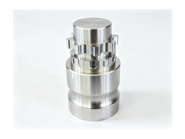
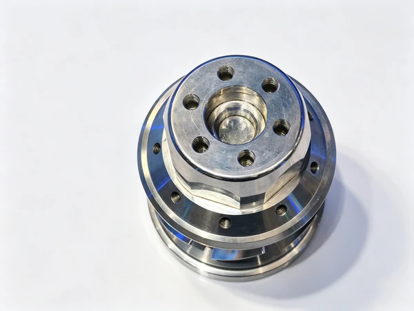
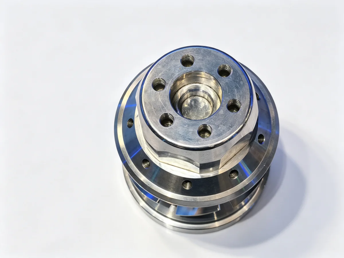
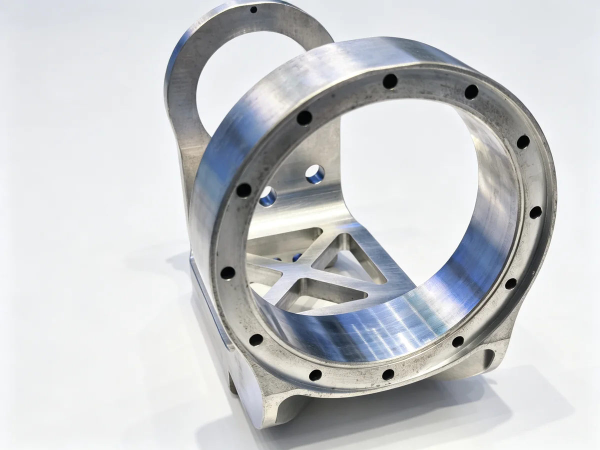
- Reducer housing. A ring or cup with a bearing seat inside, a mounting flange outside, and a bolt circle on the face. Wall thickness is set by the bearing and the bolt size, not by machining convenience, so it is thin.
- Output flange. A disc with a pilot spigot, a bolt circle, and a bore for the output shaft. Often has a labyrinth or a seal groove.
- Arm bracket or joint yoke. A fork or a ring with two ears, or an open C-shape that wraps the joint. This is the part that mixes turning and milling.
- Base plate and motor mount. Flat plate work with a large bore and a pattern of tapped holes. Simple to look at, easy to get wrong when the bore and the hole pattern come from different setups.
- Cycloidal disc. A hardened disc with a cycloid profile on the outside and a set of holes for the crank pins. This is the one part in the assembly that usually goes to a specialist, because the profile needs a grinder or a wire EDM and a heat treat step in between.
- Ring gear and pins. The internal gear that the disc runs against. Usually bought as a set with the disc rather than made in-house.
Materials and What They Do to the Process
The material choice is driven by stiffness and weight, and it changes the cutting strategy more than most drawings suggest.
Ductile iron (QT450, QT500, GGG50)
The default for reducer housings and arm brackets on industrial arms. It machines well, damps vibration, and holds a bore without springing back the way steel does. The catch is the skin. A casting arrives with a hard, sandy surface and a parting line, and if the first cut runs under that skin the insert wears on one edge only. Take a deeper first pass, or run a roughing cut around the outside before touching the bore.
Alloy steel (40Cr, 42CrMo, SCM440)
Used for output flanges, shafts and anything that takes the torque directly. It cuts cleanly when normalized and becomes unpleasant when it has been pre-hardened. For pre-hardened stock, expect lower surface speed, more attention to chip control, and a boring bar that does not chatter at the overhang you need.
Aluminium (6061, 7075)
Common on collaborative robots and on the arm tubes, where weight matters more than stiffness. It cuts fast, but a thin aluminium ring distorts from clamping pressure alone. Light jaws, low clamping force, and a spring pass on the finish cut do more for the part than a higher spindle speed.
What is missing from this list
Cycloidal discs and ring gears are usually case hardened or through hardened and then finished. If your shop does not have a grinder, that part is a buy-out, and the sensible move is to machine the housing, the flange and the bracket and leave the gear set to a supplier who does nothing else.
Why These Parts Are Awkward
Four things go wrong on robot joint parts, and all four come from the shape rather than from the drawing.
The ring is thin and the bore is interrupted. A reducer housing has a bearing seat, then a wall, then a flange with bolt holes. Boring the seat means cutting past the holes or into a pocket. The tool loads and unloads four or six times per revolution, which is exactly the condition that makes a long boring bar sing.
The two ends are related and made in different setups. The bearing seat at one end and the bolt circle at the other have to share an axis. If the part is turned between two operations and the second operation is dialed in by hand, the relationship depends on the operator that day.
The wall moves when the jaws open. A housing with 6 to 8 mm of wall, clamped at three points, is a spring. It cuts round under pressure and comes out oval. The measurement taken in the chuck tells you nothing about the part on the bench.
The bracket is not a turned part at all. An arm bracket or a joint yoke needs the bore, the ear faces and the mounting pad in one relationship. That is milling work, and on a three-axis machine it means three setups and three chances to lose the datum.
Choosing the Machine
The parts split cleanly into round work and bracket work. Trying to do both on one machine is where most first attempts go wrong.
Round parts: reducer housings, output flanges, ring-shaped brackets
These are lathe parts, and the two things that decide the machine are swing over the bed and spindle bore. Swing decides whether the housing clears the saddle when it is held on a faceplate. Bore decides whether you can bar-feed or whether every part is a blank.
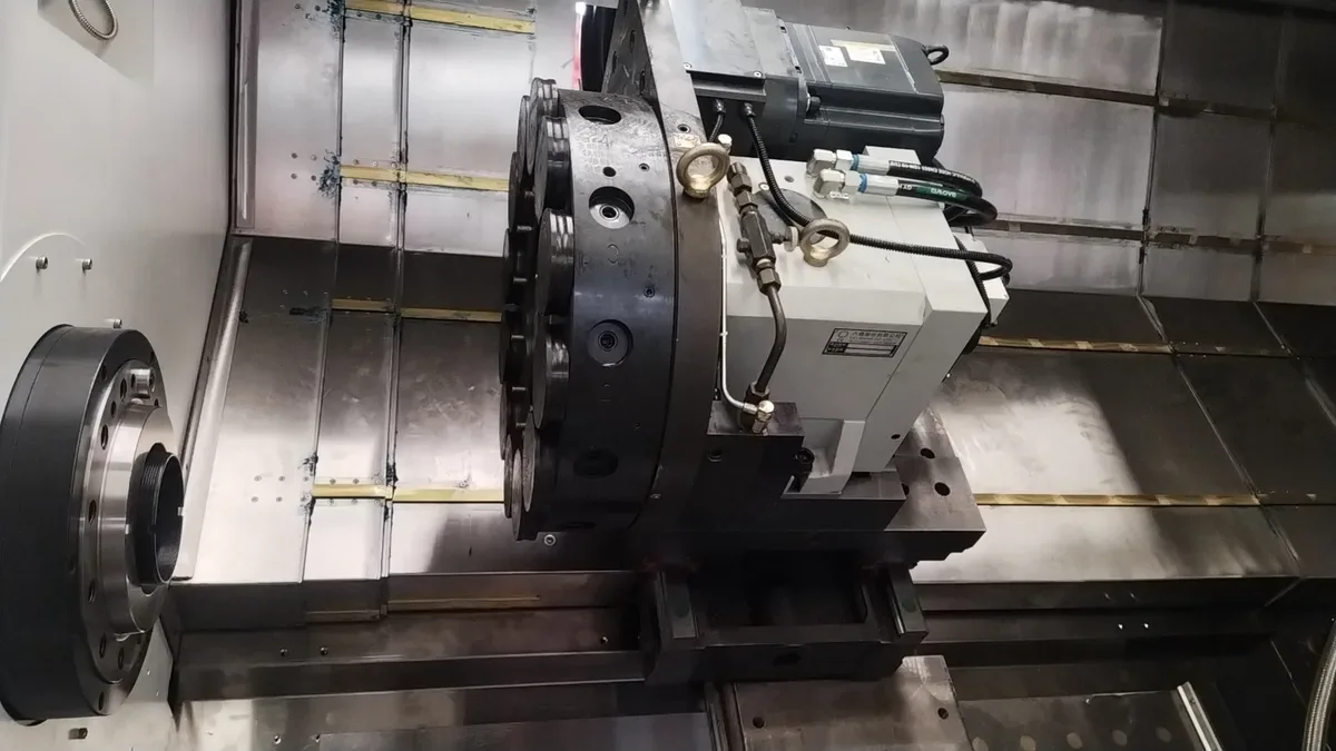
The TCK6350B is the size that covers most robot joint housings: 630 mm swing over the bed, 480 mm maximum cutting diameter, a 96 mm spindle bore, an A2-8 nose and a 10 or 12 inch chuck, with an 18.5 kW spindle motor and a 12-station servo turret. For a housing up to roughly 400 mm across, it holds the part on soft jaws with enough room for the turret to reach the bore and the face in the same cycle.
When the housing grows past that, or the batch needs a longer bed, the TCK80B-1500 takes it: 800 mm maximum cutting diameter, 120 mm spindle bore, A2-11 nose, 22 kW, 1500 mm cutting length and a 12-station turret on hardened box ways.
If the housing has cross holes, a radial port, or a tapped pattern on the flange face, the calculation changes. Doing those on a lathe means a second setup on a mill, and a second setup is where the bore and the holes drift apart. A power turret with a Y axis removes that step. The TCK56Y turns the bore, drills and taps the flange pattern and mills the cross feature without unclamping, which is the single biggest gain on this family of parts.
Bracket work: arm brackets, joint yokes, base plates
A joint yoke has a bore through it, two ear faces parallel to each other, and a mounting pad at right angles to both. On a three-axis vertical machine that is three setups: face and bore, flip for the second ear, then stand it up for the pad.
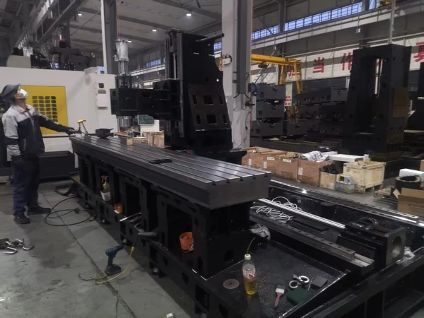
For sizes up to a 1200 x 600 mm table, the VMC1160 handles the family: 1100 x 600 x 600 mm travels, 800 kg table load, BT40 at 8000 rpm and a 24-station disc changer, on a 6500 kg ribbed casting with box ways. It is the machine most shops already have, and for a bracket that fits in one or two fixturings it is enough.
Once the part needs four faces, a horizontal is the better answer. The TH500 puts a 1200 x 600 mm table on a 7200 kg frame with 1100 / 750 / 650 mm travels and a BT40 spindle. The value is not the travels, it is the orientation: a tombstone or an angle plate turns the part instead of the operator, so the bore and the two ear faces come off one datum. On a yoke that needs four sides, that is two setups instead of four.
The Operation Order That Works
For a reducer housing, the sequence below is the one that survives a production run. It is written around a lathe with a power turret, and it adapts to a plain lathe plus a mill by moving the milling operations to the end.
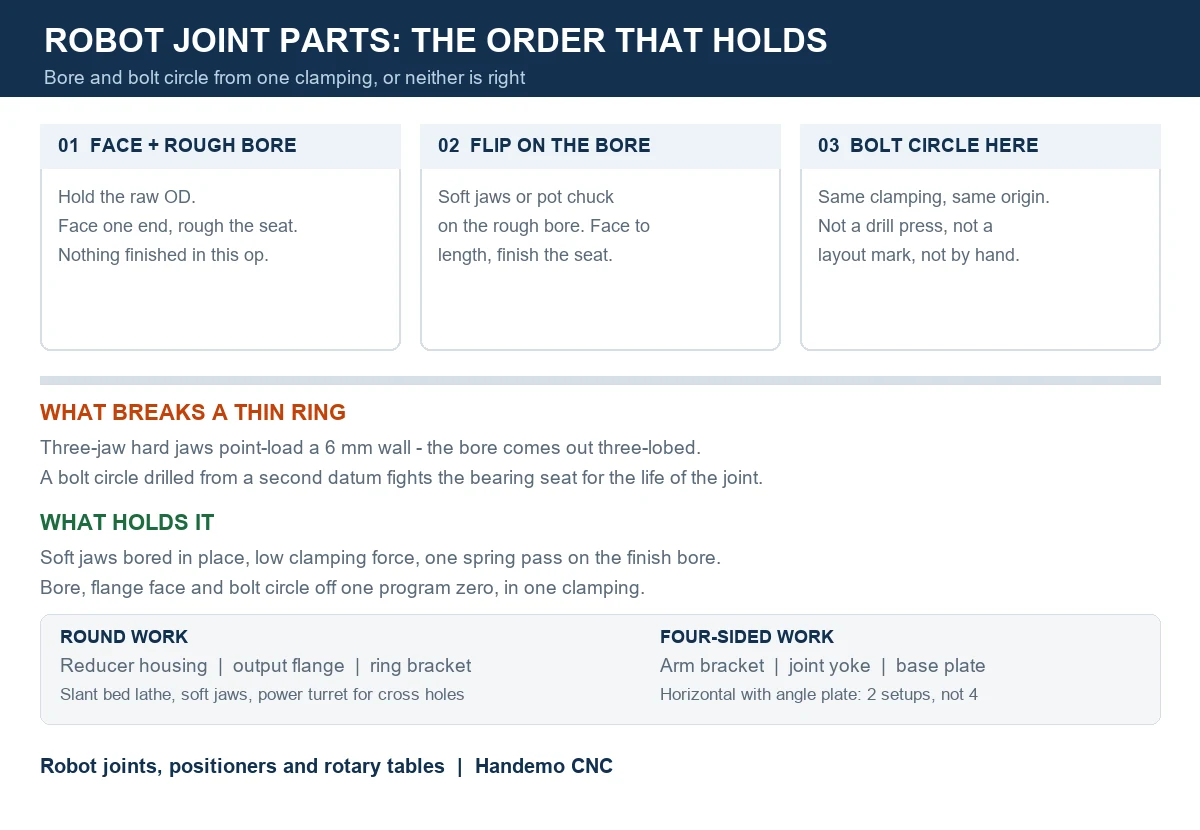
- Rough the blank on all faces. Leave stock on the bore, both end faces and the outside diameter. Break the casting skin in one pass so the inserts are not cutting sand for the rest of the batch.
- Face and rough-bore one end, holding on the raw outside diameter. This establishes the first datum and the direction of the bore. Do not try to finish anything here.
- Flip and hold on the rough bore with soft jaws or a pot chuck. Face to length, finish-bore the bearing seat, and turn the flange diameter in the same clamping. Because the seat and the flange face are cut without moving the part, the seat sits square to the face by construction rather than by adjustment.
- Drill and tap the bolt circle in the same setup, from the same program zero as the bore. This is the step that most shops move to a drill press, and it is the step that costs them the part. A bolt circle drilled from a second datum is a bolt circle that fights the bore.
- Mill the cross feature, ports or flats before the finish bore if the feature breaks into the bore. Cutting the port first and boring afterwards lets the boring pass clean up the burr the port leaves inside.
- Deburr inside the bore before the part leaves the machine. A burr at the seat edge is what the bearing sits on, and it is invisible after assembly.
For an output flange the logic is the same but the order reverses: the pilot spigot and the bolt circle belong to the same setup, and the bore is finished from the spigot side so the two stay concentric.
Clamping Without Distortion
This is where a good process and a bad process look identical on the drawing and completely different on the bench.
Three-jaw hard jaws on a thin ring point-load the part at three places. The ring cuts round while it is held, then springs back when the jaws release, and the bore becomes a three-lobed shape. The fix is not more clamping force. It is less contact pressure over more area.
- Use soft jaws bored to the part diameter in place, so the clamping load is spread over an arc rather than three points.
- For very thin rings, a pot chuck or a full-circle collet is better than any jaw. A pot chuck closes on the whole circumference and the part has nowhere to go.
- Clamp on the stiffest feature available, which on a reducer housing is usually the flange, not the wall.
- Take the finish cut with the lowest clamping pressure that still holds the part. If the part slips, the answer is a stop pin or a drive dog, not more pressure.
- Make a spring pass on the finish bore, cutting air with the same program. It removes the deflection the previous pass left in the wall.
On aluminium brackets the same rules apply with less force. A 6061 yoke clamped like a steel one comes off the machine with the ears pulled in, and the bore will not take the bearing without a press.
Holding the Bore and the Bolt Circle Together
The failure mode that shows up six months later is a joint with backlash that cannot be adjusted out. It is almost always the relationship between the bearing seat and the bolt circle, not the reducer.
Two habits keep that relationship honest. First, never let the bolt circle come from a layout mark or a hand-set position. It comes from the same program origin as the bore, in the same clamping, on the same machine. Second, when the part has to move to a second machine, transfer the datum with a fixture that locates on the finished bore, not on the outside diameter. Locating on the outside diameter means the wall thickness becomes part of the stack, and on a casting the wall is the least controlled dimension on the part.
Fixtures, Volume and the Point Where It Pays
Robot joint parts are rarely one-offs. A single arm needs six joints, a cell needs several arms, and a reducer supplier needs housings every month. Volume changes the right answer.
Under a few hundred pieces a year, soft jaws and a power-turret lathe are enough, and the fixture budget should go into one good boring bar and a set of pot chucks rather than into dedicated tooling. Between a few hundred and a few thousand, a dedicated fixture pays for itself: a plate that locates on the finished bore, holds four parts at a time on a horizontal, and lets the operator load one station while the spindle cuts another. Above that, the parts belong on a mill-turn or a horizontal with a pallet pool, and the operation order above becomes a program that never gets touched.
The other volume question is the gear set. If the customer supplies the reducer, your scope is the housing, flange and bracket, and the process above is the whole job. If the customer expects a complete joint, the cycloidal disc and ring gear have to come from a gear shop, and the schedule has to account for heat treat and finishing before assembly.
Working With a Robot Integrator
The parts themselves are not the hard part of this work. The hard part is the conversation before the first chip.
Ask which reducer the joint uses before quoting. The housing bore, the bolt pattern and the flange thickness are all set by the reducer model, and a housing machined to the wrong reducer drawing is scrap with extra steps. Ask whether the arm is a collaborative design, because a cobot joint is usually aluminium and much lighter in the wall than an industrial joint. Ask where the encoder sits, since an encoder mounted inside the housing changes the internal features and the access for the boring bar.
What a shop should not do is quote from a 3D model alone. The model will not tell you that the casting arrives with a 2 mm parting line offset, or that the flange face has draft, and those are the two things that decide whether the first operation has anything to hold.
Frequently Asked Questions
Can a robot joint housing be machined on a standard vertical machining center?
Yes, if the housing is short and the bore is accessible from the top. A vertical machine can bore and face a shallow housing in one setup. What it cannot do well is a deep bearing seat with a long overhang, because the boring bar has to reach down into the part with nothing supporting it. For housings with a deep seat, a lathe is the correct machine and the vertical is the wrong one.
Why do my thin rings come out oval after turning?
Clamping pressure at three points. The ring cuts round while it is held and springs back when released. Boring soft jaws to the part diameter, reducing clamping force and adding a spring pass on the finish cut removes most of it. A pot chuck removes the rest.
Should the bolt circle be drilled on the lathe or on a mill?
On the lathe, in the same clamping as the bore, whenever the machine has the tools to do it. Moving the part to a mill means the bolt circle and the bore come from two different datums, and on a thin housing that difference is what shows up as runout at the output flange later.
What material is normal for a robot arm bracket?
Ductile iron for industrial arms, aluminium 6061 or 7075 for collaborative arms and for anything where the arm has to be light. Steel appears on brackets that take a direct shock load. The material decides the clamping strategy more than the cutting speed.
Do I need a five-axis machine for robot parts?
Not for the housing or the flange. Those are two-axis turning work. A joint yoke with angled ear faces benefits from a fourth axis or a horizontal with an angle plate, and five-axis helps when the part has features on five sides and the volume justifies the machine. Most shops start with a lathe and a three-axis vertical and add capacity as the part family grows.
How do I keep the bore and the flange face square to each other?
Cut them in the same clamping. A single setup that finishes the face and the bore together makes the relationship a function of the machine, not of the operator. Every time the part is re-chucked, that relationship is re-established by hand, and hand work varies.
Where Handemo Fits
Handemo builds the two machine types this work needs. The slant bed lathes cover reducer housings and output flanges from a 500 mm cutting length up to a 1500 mm bed, with spindle bores from 65 mm to 120 mm, and the power-turret mill-turn models remove the second setup on parts with cross holes. The vertical and horizontal machining centers cover the brackets and base plates, with the horizontal earning its place on anything that has to be machined on four sides.
If you are quoting robot joint parts and are not sure which machine the part family belongs on, send the drawing. We will tell you which operation should run first, and which machine the part should never be put on.
Contact Handemo CNC | Email: sales1@handemocnc.com | WhatsApp: +86 135 6320 3038