CNC Machining Aluminium EV Battery Trays: Weld First
The tray came off the truck at 2.4 m long, and the first thing the operator did was lay a straight edge along the sealing face. It was not straight. Not because the extruder did anything wrong, and not because the welder was careless, but because the frame had been welded three days earlier and aluminium does not forget that. The bow was in the middle, about the width of a finger, and it ran the whole length of the part like a slack rope.
This is the normal condition of an EV battery tray when it reaches a machine shop. It is a long, thin-walled weldment made from extrusions, and every one of them arrives with some memory of the welding heat still in it. What the machining plan has to decide is not how to cut aluminium, which is easy, but how to hold a part that is already bent, cut features into it that have to agree with each other two metres apart, and hand it back flat.
Below is how we plan that job here: what the tray has to do, why the welding order matters more than the cutter, how the datum gets chosen, how the part is held without being crushed, and which machine is long enough. It belongs with the rest of our machining solutions notes, where each part family is written up the same way.
What a battery tray actually is
The name covers three different parts, and they machine differently. The first is the tray proper: a floor pan with side walls, usually an aluminium extrusion welded into a frame, with a flange around the top where the cover bolts down and a sealing groove that has to close against a gasket. The second is the cooling plate that sits inside it, which is often two thin sheets bonded or friction-stir welded into a cavity, with inlet and outlet ports and a flat top face for thermal contact. The third is the module frame or the cross-members that divide the tray into compartments.
All three share a feature list: long straight edges, a sealing or mating face that runs the full length, a set of mounting bushes or threaded inserts on a pattern that spans the part, and a floor that has to sit flat on the vehicle underbody. What matters is not any single hole. They are on the relationship between features that are more than a metre apart, which is a fixturing and datum problem rather than a machine problem.
Steel trays and die-cast trays exist too. A stamped steel tray is a press part with machined inserts and it behaves like sheet metal: it springs, and it has to be held against a form. A die-cast tray is stiffer and closer to a housing job, and if that is what you make, the EV motor housing article covers the same class of casting work.
Machine it after welding, never before
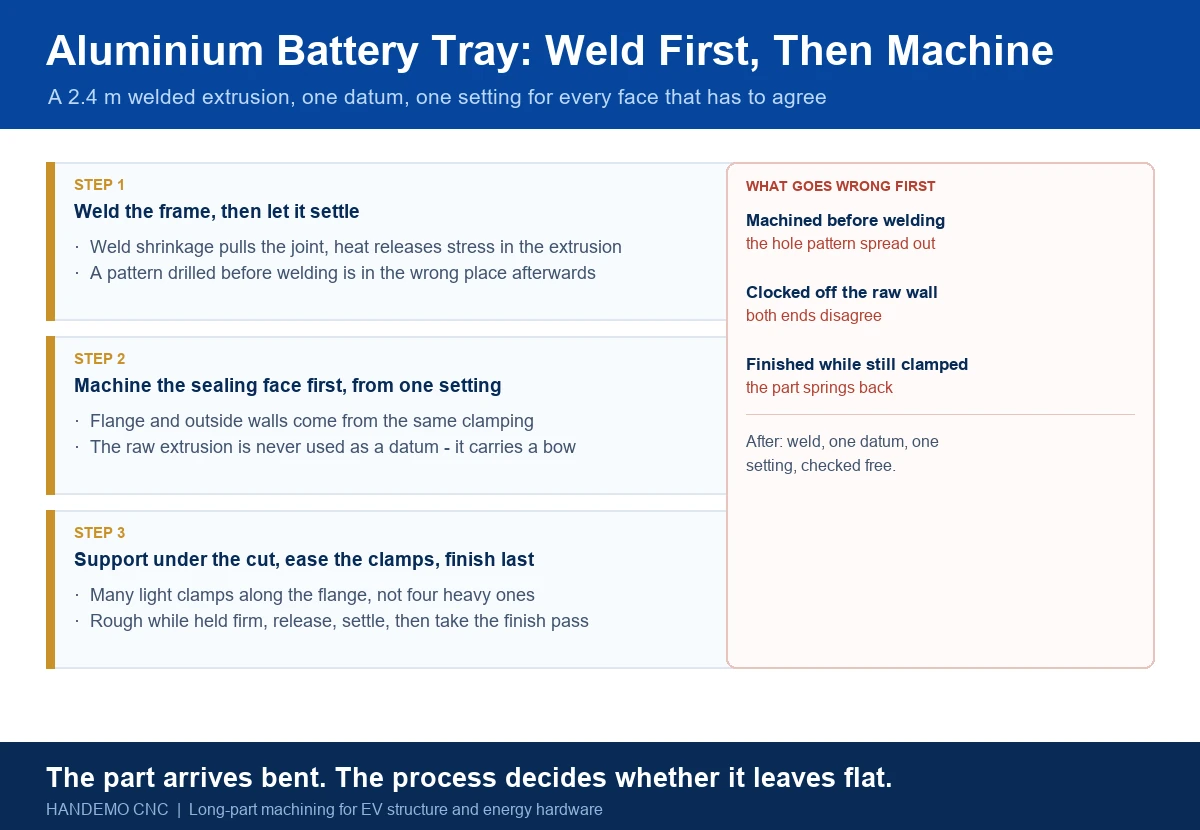
The most expensive mistake in this job is a sequence mistake, and it is made before anyone touches a machine. A shop machines the extrusion flat, drills the mounting pattern, and then sends it to welding. The frame comes back welded, the part has moved, and the pattern that was correct is now spread out or pulled in. Every hole is in the right place relative to where it was drilled, and none of them are in the right place relative to the part.
Aluminium weldments move for two reasons. The weld shrinks as it cools, and it pulls the joint toward the weld bead. The heat also relaxes whatever stress was left in the extrusion from the press, so the profile that was straight when it was cut becomes slightly curved after it has been through a weld cycle. Both effects keep going for a while after the part is cool to the touch, which is why the tray in the opening paragraph was still moving on day three.
The practical rule we work to: all welding first, then a settling period, then one machining operation that establishes the datum and cuts everything that has to agree. If a design forces welding after machining, the only reliable option is to leave enough material on the machined faces for a second pass, and to machine them again after the weld. We wrote about the same decision at length in the welded machine frame case study, where the part was 6 m long and the answer was a single finish pass after stress relief.
Choosing the datum on a part that is not flat
A tray has three candidate datums, and they are not equal. The sealing face around the top flange is what the cover closes against, so it controls whether the pack is water tight. The module mounting pads on the floor are what the cells sit on, so they control whether the modules are level and whether the thermal gap is even. The mounting bushes on the outside are what bolt the tray to the vehicle, so they control whether the pack fits the car.
We normally build from the sealing face, because it is the longest continuous feature and the one a customer will leak test. That face gets machined first, in the same clamping as the outside walls, so that the flange and the walls come from one setting. The module pads are then cut parallel to it rather than to the raw floor, and the mounting bushes are positioned from the same setting. The result is a tray whose floor is flat relative to the cover, which is what the assembly actually needs.
What we avoid is using the raw extrusion as the datum. The extrusion is the least trustworthy surface on the part: it has a bow, it has a twist from welding, and it has a seam line where the die closed. Using it as a datum means every machined face inherits the bow, and the flatness measured at the end is the flatness of the extrusion plus whatever the fixture did.
Holding two metres of thin wall without crushing it
An aluminium tray wall is often 3 mm to 4 mm thick and the floor is not much more. Clamp that with a normal vise and the part deforms under the jaw, gets machined in its deformed state, and springs back into a different shape when the clamp is released. The cut is dimensionally correct on the machine and wrong on the bench, and the argument that follows is always the same: the inspection was honest and the machining was honest, and the part still does not fit.
Three things fix it. First, support goes under the feature being cut, not at the ends of the part. A jack or a set of adjustable supports directly beneath the pad being milled means the cutting force goes into the support instead of bending the floor. Second, clamping pressure is low and spread out: many small clamps along the flange rather than four big ones, or a vacuum fixture on the floor if the part allows it. Third, the clamping is eased before the last pass on any face that carries a sealing function, and the finish cut is taken with the part as free as the process allows.
The cutting order matters for the same reason. Rough everything with the part held firmly, then release, let it settle, then finish. If the finish pass is taken while the part is still fighting the fixture, the released part carries the shape of the fight.
Cutting aluminium at this size
Aluminium is soft, which makes people treat it as easy, and on a long part it is not. The problems are chip evacuation and tool reach. A pocket in a tray floor can be 150 mm deep and 400 mm long, and at that depth the chips have nowhere to go. Recutting chips is what breaks tools and what leaves a torn surface that no amount of polishing fixes.
We run air blast as the primary chip control on these jobs, with through-spindle coolant where the tool allows it, and cutters with polished flutes and a high helix so the chip leaves the pocket instead of being pushed around inside it. Long reach is the second issue: a tool hanging 150 mm out of the holder deflects under load, and on a thin floor that deflection shows up as a taper in the pocket wall. Where the design allows, we take the pocket in steps with a shorter tool rather than reaching in one pass.
Aluminium also moves with temperature. A 2.4 m part grows measurably between a cold morning and a warm afternoon, so a tray that is cut and checked in the same hour can be different by the end of the shift. On long parts we let the workpiece sit in the shop before the finish cut rather than machining it straight off a cold truck.
Sizing the machine by table length, not spindle
Most of the enquiries we get for tray work are specified around the spindle, and the spindle is the least of it. What decides the job is how much of the part sits on the table, because that determines whether the two ends can be cut in one setting. If the machine is short, the part is done in two operations, and the second operation is where the step appears.
For trays up to about 1.4 m, a VMC1560 is the natural fit: a 2200 × 600 mm table rated to 1500 kg, X travel of 1500 mm, Y and Z of 650 mm, five 18 mm T-slots at 100 mm centres, and rapids of 24 / 24 / 18 m/min. The table is longer than the travel on purpose, which leaves room for the fixture and for the part to overhang without the spindle running out of axis.
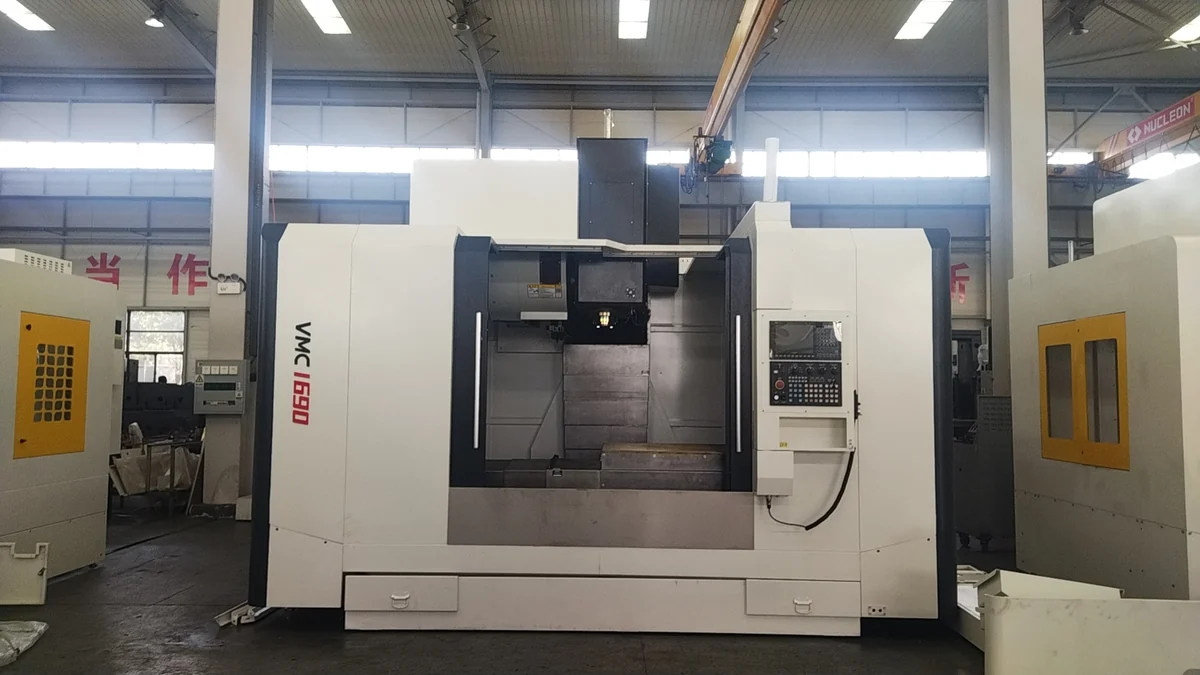
For a wider tray, or one with deep end pockets, the VMC1690 carries a 1600 × 800 mm table at the same 1500 kg rating with travels of 1600 / 900 / 700 mm and a BT50-190 spindle at 6000 rpm. The bigger taper is worth having when the pocket is deep and the tool is long, because the extra stiffness at the nose is what keeps the wall straight at the bottom of the cut.
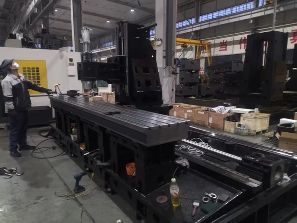
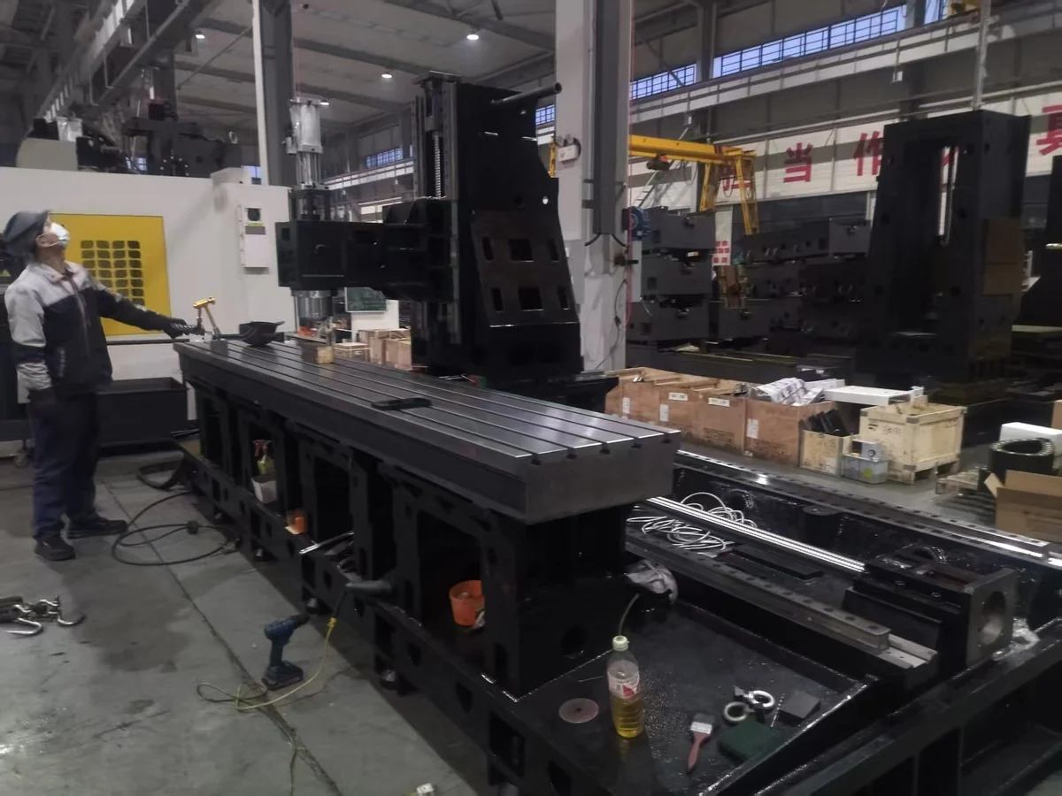
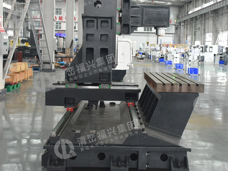
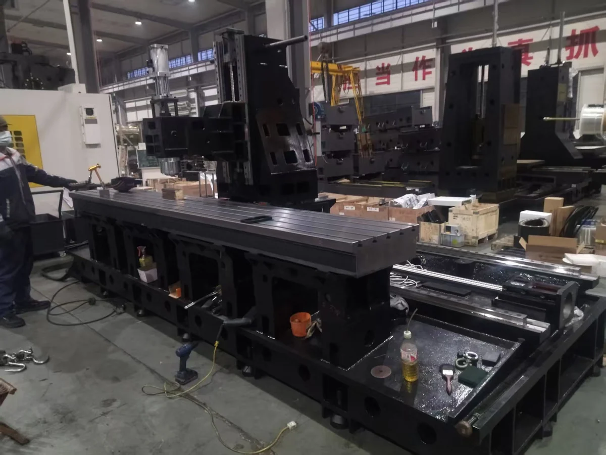
When the trays get longer than a standard vertical can cover, the answer is a machine built around length. Our double-column machines carry tables that run several metres, with the column travelling rather than the table, so a 3 m extrusion can be machined along its whole length without repositioning. The photographs in this article are from that build: the bed is a single casting with the rails bolted along its full length, and the table is one piece, because a table made in sections cannot hold a sealing face straight across a joint.
If the tray has angled ends, or ports that face sideways, a 5-axis machine removes a second operation. The LH400 takes a 400 mm table with 600 / 1000 / 600 mm travels and a BT40D spindle at 12000 rpm, which suits brackets, end plates and the smaller structural parts around a pack more than the tray itself. For the choice between a long vertical and a gantry layout in general, the gantry versus vertical comparison sets out where each one stops making sense.
Two ends, one setting, or two settings done properly
If the travel covers the part, both ends are cut in one setting and the question disappears. If it does not, the second operation has to be planned rather than improvised. The reliable method is to machine one end completely, then re-clamp on the finished features at that end and machine the other, so the second end is positioned from the first rather than from the raw extrusion. That keeps the two ends in agreement even though they were cut at different times.
What does not work is flipping the part and clocking it off the outside walls. The walls have a bow and a twist, so every tray comes out slightly different and the two ends disagree by however much the wall happened to be out that morning. On a batch, that variance is what turns a repeatable job into a sorting job.
What gets checked before the tray leaves
A tray is checked free, not clamped. The sealing face goes on a surface plate or on three points, and the gap under a straight edge is measured along its length; the number that matters is the gap after release, because that is the shape the customer will bolt down. The module pads are checked the same way, and their height relative to the sealing face is checked with a height gauge rather than assumed from the machine.
The mounting bushes are checked on the pattern, with a jig that carries the vehicle-side hole positions if the customer has one, because a bush that is right on its own and wrong in the pattern is the failure that shows up at the assembly line. A cooling plate version gets a leak test before anything else, since a cavity that leaks makes the flatness irrelevant. And on the first part of a batch we ask for a trial fit of one module, which catches more than any drawing check.
Material and thickness notes
Most trays are 6000-series extrusion, typically 6061 or 6082, with the floor and walls in one profile and the ends closed by welded plates. The extrusion temper matters: T6 cuts cleanly and holds its shape, while a softer temper will smear and will move more once the skin is removed. Where a tray is specified in 7075 for a structural version, the cutting is still aluminium but the part is stiffer and less forgiving of a fixture that does not support it evenly.
Cast trays and cast end plates behave differently again, and the casting has to be proof machined before the pattern is committed, because a casting that cleans up on one face may not clean up on the other. That is the same discipline as any housing job, and the thin wall parts article covers the wall thickness side of it.
What to put on the enquiry
A drawing and a quantity get a price. A drawing plus four facts gets a process. The four are: whether the part is welded and when, which face the cover seals against, how the tray is supported in the vehicle, and how long the part is overall. With those we can say whether it runs in one setting or two, which machine it goes on, and what the fixture will look like. Without them we can only quote a number and hope the assumptions hold.
We have been building machines for this class of work since 2008, in a 220,000 m² plant, and a fair share of what leaves here goes to shops making EV structure and energy hardware in more than 150 countries. The parts in these photographs were cut on our own machines, which is the only way we can tell a customer honestly what a long table does for a part that arrives bent.
Questions we get asked
Can a standard vertical machining center machine a battery tray?
Up to about 1.4 m, yes, and a VMC1560 with its 1500 mm X travel is a sensible choice. Beyond that the part needs either a longer machine or two settings, and two settings need a datum carried from the first, not a re-clock off the outside.
Why not machine the extrusion before welding?
Because the weld moves the part. Shrinkage pulls the joint and the heat releases stress in the extrusion, so a pattern drilled before welding is in the wrong place afterwards. Weld first, let it settle, then machine everything that has to agree in one operation.
How do you stop a thin floor from being crushed in the fixture?
Support it under the feature being cut, spread the clamping over many points along the flange, keep the pressure low, and ease the clamps before the finish pass. A part that is finished while fighting the fixture comes out in the shape of the fight.
Do you machine the cooling plate as well as the tray?
Yes. A cooling plate is a flatness and leak job more than a cutting job: the top face has to sit against the modules, the ports have to be clear, and the cavity has to hold. It is usually machined on the same long machine as the tray so both come from one datum.
What length can you actually cover in one setting?
It depends on the table, and the table is what we size first. Our double-column machines run tables of several metres with the column travelling, so a 3 m extrusion is machined along its full length without repositioning. Tell us the part length and we will tell you which frame covers it.
Contact Handemo CNC | Email: sales1@handemocnc.com | WhatsApp: +86 135 6320 3038