CNC Machining Flywheels and Belt Pulleys
A flywheel is a heavy disc that stores energy, and a belt pulley is a light disc that transmits it. Buyers treat them as two different products, and on the shop floor they are the same job twice: a disc with a bore, a face, and something on the outside that has to line up with the bore. The failures are the same too. Nobody sends back a pulley because it was 2 mm under on the outside diameter. They send it back because the belt walks off the grooves, or because the flywheel shakes the machine it is bolted to.
We turn flywheels and pulleys for engine and compressor builders, for agricultural drive units, for fan and blower makers, and for maintenance shops that replace one part at a time. What they ask for is a diameter and a bore and a delivery date. What decides whether the part runs is the order the three features are cut in, and whether the outside of the disc follows the bore or the bore follows the outside.
This article covers the family: what counts as a flywheel or pulley job, which materials come through the door, how the sequence should be planned, and where a slant bed lathe does the work and a machining center has to step in. It sits alongside the rest of our machining solutions notes, where each part type is written up the same way.
What counts as a flywheel or pulley job
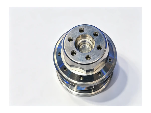
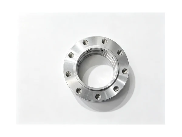
The names overlap more than the drawings suggest. A solid flywheel for a single cylinder engine is a plain disc with a bore, a keyway and a ring of bolt holes, and its whole job is mass. A two-piece flywheel has a cast or forged centre bolted to a steel plate, and then the balance of the assembly is decided by the bolt circle, not by either part alone. A ring gear type flywheel carries a hardened toothed ring shrunk or bolted onto the rim, and the teeth are bought in, so the machining is all in the centre.
On the pulley side, a single groove V-belt pulley is a disc with one groove and a bore. A multi-groove pulley is the same part stacked, and the pitch of the grooves is what the belt cares about. A taper lock pulley has a plain bore and a split tapered bushing doing the gripping, which means the bore is easy and the outside still has to run true. A flat belt pulley is a plain crowned drum. And a timing pulley looks like a pulley but is really a toothed part, so it belongs with the sprockets and gears rather than here.
The families that come through our floor most often are the cast iron flywheel, the steel plate flywheel, the V-groove pulley in one to six grooves, and the taper lock hub and pulley pair. All four start as a turning job, and how much milling sits on the end of it depends on the drawing.
Materials, and what each one does to the plan
Cast iron is still the natural material for a flywheel or a large pulley. It damps vibration, it is cheap in volume, and a GG25 or similar casting comes in with enough stock to clean up. The catch is the skin and the variation: a raw casting is not round enough to indicate from, so the first operation is normally to grip the rough outside, face one side and establish the bore. Only after that does the outside have a centre to be turned from. Castings also arrive with hard spots, and a hard spot in an interrupted cut is what breaks a turning insert at the wrong moment.
Mild and medium carbon steel, 1045 being the usual one, is what we see for steel plate flywheels and for pulleys that will be welded into an assembly. It turns cleanly, it can be flame cut or laser cut as a blank, and it takes a keyway without argument. A flame cut blank has a hard edge, so the first pass usually has to get under it rather than through it.
Alloy steel such as 4140 appears where the flywheel is also a drive component and the bore carries a load. It is tougher than 1045, it will work harden if the tool rubs, and it is usually supplied pre-hardened, which means the finishing passes are lighter and the tool grade matters more than the speed.
Aluminium shows up on small pulleys for light drives, on prototype fixtures and on anything where rotating mass has to come down. It machines fast enough that the limit is usually chip evacuation rather than the tool. Stainless grades appear on food and washdown equipment; they smear if the feed is too light, and they move more than steel when the part is a thin disc.
Why the sequence decides the result
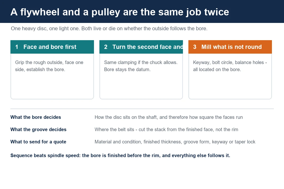
Almost every complaint we get about a disc part comes down to which feature was used as the datum. The drawing shows a bore with a keyway, two faces, a rim and a bolt circle. If the disc is turned between centres first, then the bore is drilled from the outside, then the bolt holes are drilled from the outside, you can end up with three features that each agree with the outside diameter and none of them agreeing with each other. That part bolts on, and then the belt runs to one side of the grooves because the grooves were the reference.
The route that lasts is the one where the bore is established first and everything after it is cut from the bore. Face the first side, bore the pilot, then turn the second side and the rim from the same clamping where possible. If the disc is too large to hold through one clamping, the finished bore and the finished face become the datum for the second setup, which is why a bore that has been finished early is worth more than a face that has been finished early.
The other decision is when the keyway is cut. A keyway has to be parallel to the bore axis and on centre. Cut it in the lathe with a broach in the turret, or cut it on a machining center with the part located on the bore, and either is fine. Cut it last in a vice with the part held on the rim, and the keyway is as good as the rim, which is not the reference the shaft sees.
Where a slant bed lathe fits
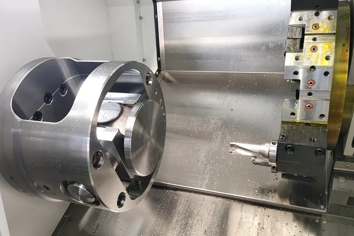
Disc parts are turning work first. Our TCK6350B heavy-duty slant bed lathe swings 630 mm over the bed with a 96 mm spindle bore, takes bar up to 85 mm, and runs a 10 or 12 inch chuck on an 18.5 kW spindle with a 12 station servo turret. That envelope covers most cast iron flywheels and pulleys up to the range where the part has to be lifted rather than chucked, and the slant bed lets the chips fall clear instead of packing under the part, which matters when you are peeling a casting skin.
For smaller pulleys and hubs, the TCK50 slant bed lathe covers discs up to 500 mm over the bed with a 65 mm bore and an 8 station turret. It is the machine we put a batch of V-groove pulleys on when the grooves are formed with a single plunge tool and the whole family is under a few hundred millimetres. At the heavy end, the TCK6350D runs a 22 kW spindle with a 630 mm swing for larger discs that also need a bigger depth of cut to get through a cast skin in reasonable time.
The reason to put this work on a slant bed rather than a flat bed lathe is not the angle. It is that the part is short, heavy and held in one clamping for most of its features, so the machine has to be stiff enough that the first roughing pass on a rough casting does not push the part away. A disc that deflects under the first pass comes out with a thickness that tapers across the face, and a pulley with a tapered face runs its belt to one side.
Where a vertical machining center earns its place
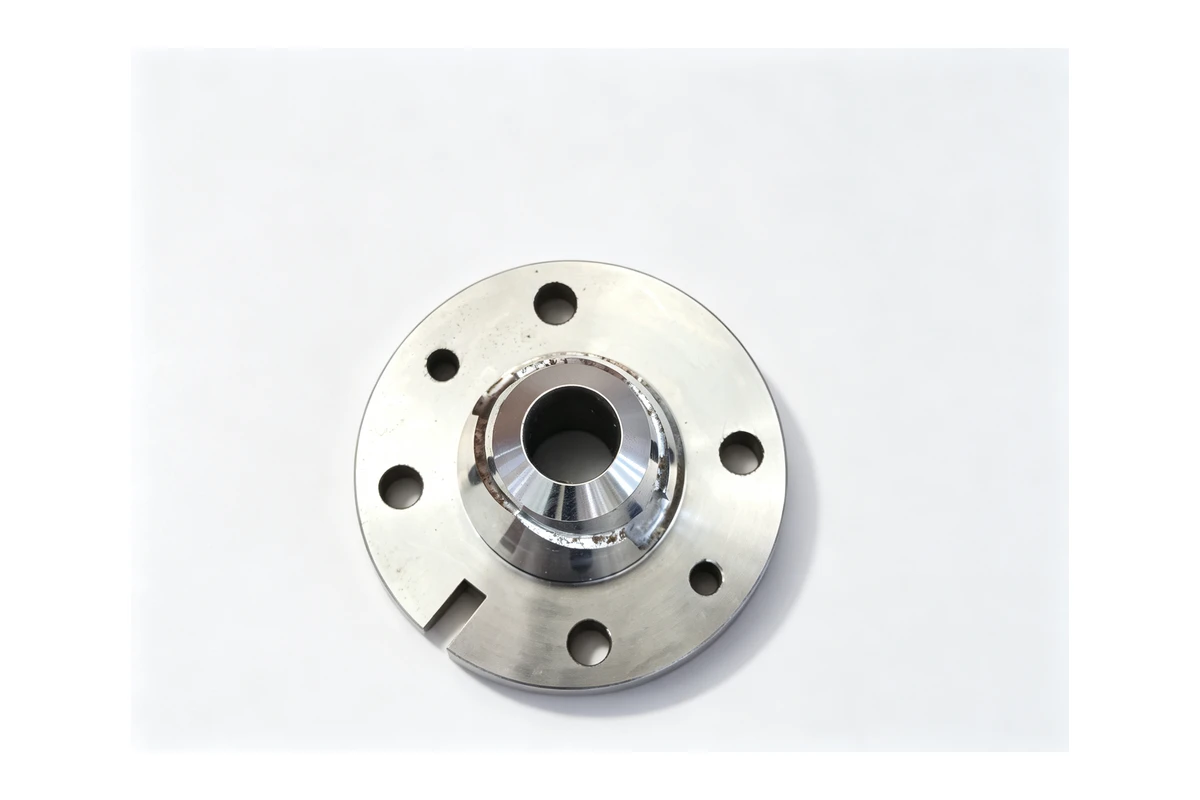
A lathe turns round features, so everything that is not round goes to a mill. On a flywheel that means the bolt circle if it is drilled rather than turned, the keyway if it is not broached, and the balance holes. On a pulley it means the keyway, the tapped holes for a taper lock bush, and any set screw or grub screw position.
For discs up to about 500 mm, a VMC855 covers the milled side in one setup. The table is 1000 x 550 mm rated at 600 kg, travels are 800 / 550 / 550 mm, and the BT40 spindle runs to 8,000 rpm. A 400 mm flywheel sits flat on the table on a fixture plate with the bore locating it, and the bolt circle, keyway and balance holes all come off the bore in one clamping.
Above that, the VMC1160 opens the table to 1200 x 600 mm rated at 800 kg with 1100 / 600 / 600 mm travels and the same BT40 spindle. A 600 mm pulley or a flywheel with a ring gear flange is a normal job on that table, and the part can be supported across its full face instead of hanging off an edge. That support is what keeps the two faces parallel when the bolt holes are drilled from the machined side.
Two things to flag about the milled side. First, balance holes are a machining decision, not a drawing formality. They are drilled after the part is finish turned and after the bore is final, from the same datum, or they correct nothing. Second, a keyway cut on a machining center should be cut with the part located on the bore and the finished face, not on the rim, because the rim runout on a casting is exactly what you are trying to clean up.
The operations that cause trouble
The bore and its keyway. The bore is the reference for everything else, so it is worth finishing it before the rim. A bore that is finished after the rim has been turned from the rough outside inherits whatever the rough outside was doing. On a thin hub the boring pass itself will bell-mouth the bore if the tool is fed too hard, and a bell-mouthed bore puts the whole disc out of square on the shaft.
The groove form. A single V groove is a plunge with a form tool, and the tool has to be dressed and set once for the whole batch. Where the job goes wrong is on a multi-groove pulley: cutting the grooves one at a time from the face leaves an accumulated position error across the stack, so the belt sits on two grooves and skims the rest. Cutting them from the finished face, with the stack dimensioned from that face, holds the family together.
The rim and the web. A large pulley is turned with a web and often a set of lightening holes to reduce mass. Drill those holes after the bore is established, from that datum, or the disc comes out heavy on one side and the machine it drives feels it as a once-per-revolution pulse. On a pulley running at speed, an unbalanced disc is audible before anything can be measured on it.
Casting variation. Cast flywheels arrive out of round, with draft on the faces and hard spots in the skin. The first operation is to face one side and establish the bore, using stock that will actually clean up. That is why cast parts need an allowance on the drawing: a casting that comes in with the rim dimension already at finished size has nowhere to go once the bore is set.
Holding consistency across a batch
A drive unit does not care about one pulley. It cares that the replacement fits the shaft, sits in the same plane as the mating pulley, and does not change the belt tension. That is a consistency question, and it is answered before the first cut: the same fixture, the same datum, the same first-off check on the bore, the face and the groove position, and a record of it that travels with the batch.
On a run of fifty pulleys, the variable that drifts is not the lathe. It is the chuck jaws and the fixture. Soft jaws bored for one outside diameter lose their concentricity the moment they are re-bored for the next size, and a fixture that is cleaned once a shift holds a part differently at the start of the shift than at the end. The shops that hold a batch together treat the fixture as part of the job and keep it with the batch number rather than with the machine.
We build our turning centers around that reality: a rigid slant bed, a spindle sized for the depth of cut the material needs, and a turret with enough stations that the groove tool, the boring bar and the drill can all stay set for the run. The milled side of a disc part usually lands on the same vertical machines we cover in the rest of the machining solutions series, and the toothed version of the same problem is written up in our sprocket machining note.
What to put on the enquiry
Most flywheel and pulley enquiries arrive as an outside diameter, a bore and a quantity. That is a start. What changes the quote is the material and whether it is a casting or a plate blank, the finished thickness, the groove form and count if it is a pulley, whether the bore has a keyway or a taper lock bush, the bolt circle if there is one, whether balance holes are needed, and whether the part is a single disc or one half of a bolted assembly.
If the disc is balanced as an assembly, say so. Balance is a property of the whole rotating group, and a part that is balanced on its own can still put the assembly out. If a part has failed in service, the failed part is more useful than the drawing, because the wear pattern tells us whether the problem was the bore, the face or the groove.
Questions we get
Can a flywheel be turned completely on a lathe?
The round features, yes: both faces, the rim and the bore. The keyway, bolt circle and balance holes need a mill or a broach, unless the lathe has a turret with live tooling. For most discs the practical split is turning for the round work and one milling setup for everything that is not round.
Should the grooves be cut before or after the bore is finished?
After. The groove position has to be measured from the finished face, and the face is only meaningful once the bore is final. Cutting grooves from a face that is still moving with the casting skin gives a pulley that runs true in the chuck and walks the belt once it is on the shaft.
How do you stop a pulley from wearing on one side of the belt?
Check the two faces and the bore first, then the grooves. A pulley whose bore is not square to its face runs tilted, the belt loads one flank of every groove, and the wear appears on one side of the belt. The groove profile itself is rarely the cause on a pulley that ran correctly for a long time.
Do you need balance holes on every flywheel?
No. Small discs and low speed drives are usually fine as turned. Balance holes earn their place on large diameter parts, on assemblies that run at speed, and on castings that come in with wall thickness variation. Where they are used, they are drilled from the finished bore and finished face, in the same setup as the bolt circle.
What batch size makes a dedicated fixture worthwhile?
Around twenty pieces. Below that, soft jaws and a first-off check are cheaper than a plate. Above that, a fixture that locates on the bore and the back face pays for itself in setup time alone, before any gain in consistency across the batch.
Next step
Send the drawing, the material and its condition, and the batch size, and tell us which face sits against the mating part. If it is a pulley, tell us the belt section and the groove count. We will come back with the setup plan, the machine, and a price that includes the fixture if the batch justifies one. Contact Handemo CNC | Email: sales1@handemocnc.com | WhatsApp: +86 135 6320 3038