Case Study: Machining Welded Machine Frames
The frame arrived on a flatbed with a crane at each end and a drawing taped to the top rail. It was a welded steel base for a packaging line: two long rails, four cross members, a plate deck on top, motor pads on one end and a set of bearing bores at the other. Measured with a straight edge on the welder's bench, it looked perfect. Set on the machine table and clocked at the four corners, it rocked.
This is the part of the job that purchase departments rarely see. A weldment is straight when it is welded and moves while it cools, and nothing about that is a mistake by the fabricator. The frame had already been stress relieved, and it had still come back with the pads out of flat and the rails with a gentle bow along their length. The customer's problem was not the weld. It was that the pads were going to be bolted to a floor and the bores were going to hold a shaft, and both of those things care about a plane that the weld does not know about.
What follows is how a frame of that family was machined here, in two setups, and what actually decided the route. It is part of our case studies series, where each article follows one real part through the floor and explains the decisions rather than only the result.
What the part actually is
The frame was roughly 2,600 mm long, 1,100 mm wide and 700 mm tall, welded from square tube and plate in structural steel, and it weighed a little over 900 kg when it came in. It was not a machined casting with a few surfaces cleaned up. It was a fabrication that needed a set of surfaces created from nothing.
The work was concentrated in four places:
- Four floor pads under the rails, each about 120 x 120 mm, which had to sit in one plane so the frame would not rock once it was bolted down.
- A deck plate on top with a pattern of tapped holes for the conveyor mounts, plus two machined strips where the guide rails would bolt on.
- A motor mounting face at one end, square to the axis of the drive, with four tapped holes and a bore for the shaft.
- Two bearing bores at the other end, in line with each other and with the motor face, because a shaft runs through all three.
That last line is the whole job. The pads only have to agree with each other. The motor face and the two bores have to agree with each other and with the pads, because the frame is bolted to a floor at one end and carries a rotating shaft at the other. If the bores are cut from one datum and the pads from another, the assembly either shims or the shaft binds, and the argument about whose fault it is starts on the customer's site.
Machine bases and beds are a related family with a different set of problems, mostly because they are castings and much heavier. We covered that side of the work in CNC machining machine bases and beds. A weldment adds two things that a casting does not: the frame moves because of residual stress from the weld rather than from the pour, and it is hollow, so it rings and deflects under clamping in ways that surprise people.
The material, and why it changes the plan
Structural steel for a frame like this is usually S355 or a Q235 equivalent, sometimes S275 for lighter frames, welded with a mix of fillet and full-penetration joints. It is mild, it cuts easily, and it is not the difficulty. The difficulty is what welding did to it.
Every weld shrinks as it cools, and a frame with forty metres of weld in it pulls itself into a shape that no longer matches the drawing. The fabricator stress relieves the frame afterwards, which releases most of the locked-in stress, but relieving does not straighten anything. It only stops the frame from moving again later. So the machine shop receives a part that is dimensionally close and geometrically crooked, and the first machining operation exists to create a true face rather than to remove a known allowance.
Two practical consequences follow. First, the stock allowance on the pads and on the deck has to be generous, because the frame may be leaning more than the drawing suggests, and a pad machined to final size on the first pass has nowhere to go if the opposite corner is low. Second, the frame should be machined after stress relief and not before. A frame that is machined and then relieved will move, and everything cut into it goes with it.
Occasionally a customer asks for the frame to be machined and then galvanised or painted. That is fine, but the sequence matters: machine, then treat, then check the pads. Hot-dip galvanising puts a coating on the pad faces, and if the pads were the reference for the assembly, the reference has just changed thickness.
Why the frame arrives out of flat
It helps to be specific about what "out of flat" means on a weldment, because it is not one fault.
The rails bow along their length after welding because the weld on the neutral axis shrinks more than the steel around it. The cross members pull the rails toward each other, so the frame is slightly narrower in the middle than at the ends. The plate deck, welded on one side only, cups upward. And the pads, if they were welded on as separate pieces, sit at slightly different heights because each one was fitted by hand.
Add the thermal side. A frame that is brought into a warm shop from a cold yard will change shape for a few hours as it equalises, and a frame that is clamped while it is still cold will be machined in a shape it will not keep. This is the same reason a large plate should be allowed to settle before the finishing cut, and it is why our own scheduling leaves weldments on the floor overnight before they go on a machine when the weather is cold.
None of this is a defect in the frame. It is the nature of the process, and the machining plan is what absorbs it.
The two setups
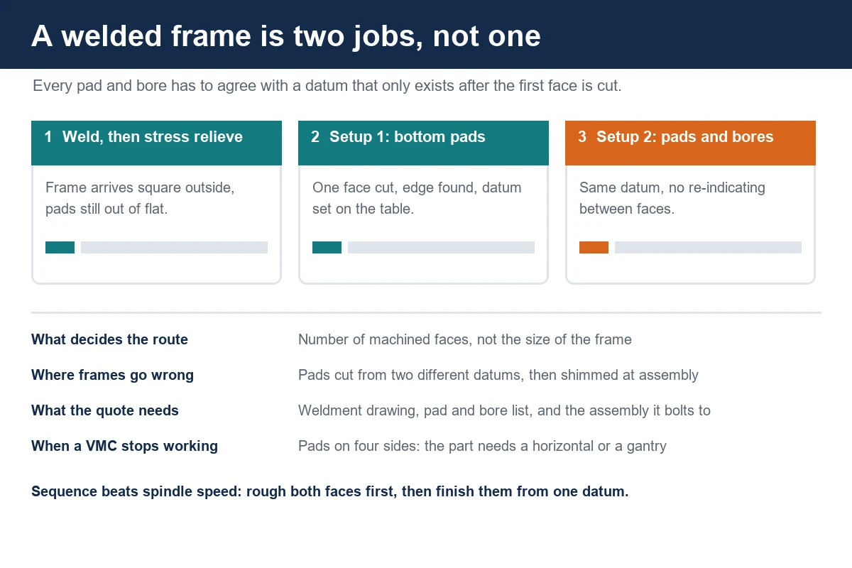
The route we used was two setups on a horizontal machining center with a rotary table, and the reason for the horizontal rather than a big vertical was not size. The frame would have fitted on a large VMC table. The reason was that the pads are underneath and the deck, the motor face and the bores are all above and at the ends, and on a horizontal the part can be rotated between faces without being lifted off its datum.
Setup one put the frame upside down on the table, clamped on the rails rather than on the pads, with the four floor pads facing the spindle. The face of each pad was cut first, and only then were the pads brought to a common height. The order matters: cutting all four in one pass with a face mill leaves them in one plane by construction, whereas cutting them to a number measured off the top of the rail inherits every error in the rail.
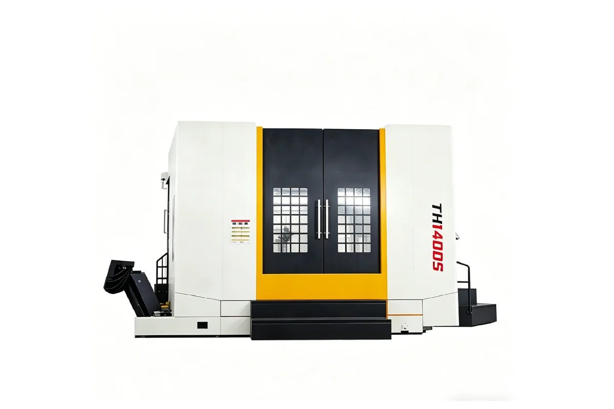
Setup two turned the frame over onto the finished pads, which had by then become the only datum in the job. The deck was faced and the tapped pattern drilled, the guide rail strips were machined, the motor face was milled and its bolt pattern and bore cut, and the two bearing bores were bored from the same side without moving the part. On a machine with a 1,400 x 1,400 mm table and 5,000 kg capacity, such as the TH1400S, the frame sits entirely on the table with room to spare, so the rotary index between faces never asks the crane for help.
The same logic works on a smaller frame on a machine like the HMC1000, whose 1,000 x 1,000 mm table and 3,500 kg load rating cover most packaging and general machine frames. The limit is not the table size but the reach: a 2,600 mm rail on a 1,000 mm table means the ends overhang, and an overhanging rail will deflect under the cut unless it is supported.
Holding a weldment without chasing it
A welded frame is a spring with a bad attitude. Clamp it hard in the middle and the ends lift. Clamp the ends and the middle sags. Either way, the frame is straightened by the fixture, machined straight, and then springs back when the clamps come off, which is the classic way to produce a frame that was perfect on the machine and is not perfect on the floor.
Three things kept that from happening here:
- Clamping over the supports. Every clamp sat directly above a jack or a block, so the clamping force went into the support and not into bending the rail.
- Supporting the frame on more than four points. Six supports, shimmed to a straight edge, with the middle pair just touching, keep the rails from sagging between the ends.
- Roughing before finishing, and re-checking the datum between the two. The first cut releases stress in the weld and moves the frame a little; the finishing cut then happens on a frame that has already moved.
The same discipline appears on thin-wall parts, where the answer is also to control where the material gives rather than to clamp harder. We wrote about that in CNC machining thin-wall parts, and the underlying idea is identical.
Bores and pads that have to agree
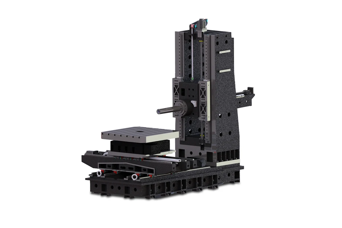
The bearing bores and the motor face are what made this job interesting. On a casting, the bore and the mounting face are often machined in one setup because the casting has enough stiffness to be flipped without losing the reference. On a hollow weldment, flipping is exactly what you want to avoid.
Our approach was to cut the motor face and the two bores with the frame in one position in setup two, so the relationship between them came off the machine's own geometry rather than off the part. Boring both bearing bores from the same side through the same spindle axis, then milling the motor face at the same index, means the three features are as aligned as the machine is, and the alignment does not depend on how well the operator re-indicated a welded surface.
If the frame cannot be positioned that way, the alternative is to bore one end, index the table, and bore the other, which puts the rotary table's positioning into the chain. That is acceptable on a machine whose table is in good condition and is a risk on one that is not, which is why we prefer to keep the two bores in one index whenever the travel allows it.
Why not a vertical machine, or a gantry
A large vertical machining center would have done the top work comfortably. The VMC1690, with a 1,600 x 800 mm table, 1,500 kg load rating and BT50 spindle, is a natural fit for deck plates and frames that only need one face. What it does not like is the underside, because the part has to be lifted off and turned over, and every flip on a 900 kg weldment is a chance to lose the datum and an hour of crane time.
A gantry would also work, and for frames longer than about four metres it becomes the sensible answer. We compared those two routes in gantry vs vertical machining center. Below that length, a horizontal with a rotary table usually wins on setups rather than on travel, because the part stays clamped while the machine indexes.
The wider question of how many faces carry work is the same one that decides any box-type part, and we went through it in how to choose a machining center for box and housing parts. A frame is a box with the panels missing: hollow, open, and awkward in exactly the same way.
What the customer measured afterwards
The customer tracked three things on the first eight frames: crane lifts, setups, and how many frames needed shimming when the line was assembled.
Lifts went from three per frame, in their old route, to one. Setups went from four to two. Shimming at assembly went to zero on all eight, which they attributed to the pads and the bores finally coming off one datum instead of two. The other change they noticed was on their own floor: because the frame no longer arrived with a bow in the rails, the conveyor guide rails could be bolted on without being packed out at the middle.
That last effect is the one that is hard to put in a quote and easy to feel in production. A frame that is flat when it arrives removes a shimming step from every machine the customer builds on top of it.
What decides the quote on a frame job
Four things move the price on a weldment more than anything else:
- The number of faces with work on them. One face is a vertical job. Two or three faces on a part too heavy to flip comfortably is a horizontal job. Four sides plus the ends is a different conversation again.
- Whether the frame has been stress relieved. An unrelieved frame will move during machining, and the shop either adds a roughing pass and a settle, or eats the rework.
- The stock allowance on the pads and deck. A frame flame-cut close to size with generous pad stock is a straightforward job; one welded with the pads already at finished height is a repair job wearing a new part's clothes.
- Whether the bores have to line up with each other. Two bores in line is a boring operation with a plan. Two bores roughly in the right place is a drilling operation.
Send the weldment drawing, the pad and bore list, and the assembly drawing the frame bolts into if you have it. The frame drawing tells us the size; the assembly tells us which surfaces are actually references and which are just steel. Drawings can go through our drawing upload page if email is inconvenient.
FAQ
Do you machine welded frames or only castings?
Both. Weldments in structural steel and cast iron bases and beds go through the same floor, and the planning question is the same one in each case: which face becomes the datum, and how many times does the part have to be picked up.
Should a frame be stress relieved before or after machining?
Before. Stress relief releases the locked-in stress from welding and lets the frame settle, but it does not straighten it. Machining after relief means the surfaces that are cut stay where they were cut. Machining before relief means the relief moves everything you just made.
Can a welded frame be machined on a vertical machining center?
Yes, when the work is on one face, or when the frame is light enough to turn over without losing the datum. Once pads, bores and mounting faces sit on two or three sides of a part that needs a crane to flip, a horizontal machine with a rotary table usually removes setups rather than adding cost.
How do you stop a frame from springing back after machining?
By clamping over the supports instead of between them, supporting the part on more than four points so it cannot sag, and roughing before finishing so the frame moves while there is still material to remove. A frame that is straightened by the fixture and machined in that shape will spring back the moment the clamps come off.
What do you need to quote a frame machining job?
The weldment drawing with the pad and bore details, the material and whether it has been stress relieved, the finished thickness or height on the machined faces, the assembly drawing if the bores have to line up with anything, and the batch size. If the frame is part of a line, send the whole line in one enquiry so the datum chain can be planned together.
Frames, bases and the parts that bolt to them are the kind of work we do every week. If you have a weldment that will not sit flat or a bore that will not line up, send the drawing and we will come back with a route and a price. Contact Handemo CNC | Email: sales1@handemocnc.com | WhatsApp: +86 135 6320 3038