Case Study: A 1600 mm Mold Base Plate in Two Setups
The drawing that started this job was four sheets stapled together: a cavity plate, a core plate, a stripper plate and a set of guide pillars. The customer, a toolroom that builds compression moulds for appliance housings, had been machining the plates on a mid-size vertical machining center for years. Nothing was wrong with their work. What was wrong was the calendar. Every plate went through four clamps, and by the fourth one the operator had spent more time indicating the block than cutting steel.
They did not come to us asking for a bigger machine. They asked whether the plate could be done in two setups, because the four-setup route was eating the days they needed for fitting. The answer was yes, but not because of the spindle. It was because the table was long enough to keep the plate on one datum from the first roughing pass to the last pocket.
This case is part of our case studies series, where each article follows one real part through the shop floor and explains the decisions, not just the result.
What the part actually is
A mould base is not one part, it is a stack. The cavity plate carries the female form. The core plate carries the male form and the ejector pattern. The stripper plate sits between them. The backing plates close the stack and take the load from the injection pressure. Around the outside sit the guide pillars, the guide bushings, the return pins and the sprue bush, and every one of those features has to line up through 200 to 400 mm of stacked steel.
That is the thing buyers underestimate. A single plate can be made well and the stack can still fight, because the guide pillar holes were bored from a different datum on each plate. The plates are not four jobs. They are one job with four pieces.
We wrote a separate guide to the plate family itself, covering the steels and the order of operations, in CNC machining mold bases. This article is the shop-floor version of the same job, with the numbers that came off one plate.
The plate in this case was 1600 x 800 x 180 mm in the rough, finished at 1600 x 800 x 160 mm. It carried a cavity pocket roughly 900 x 500 mm, two guide pillar bores at diagonal corners, four return pin holes, a sprue bore, a water line circuit around the pocket, and a pattern of tapped holes for the insert clamps.
The materials, and why they change the plan
Most mould and die bases in this size range are cut from pre-hardened plate: P20, 718, or a 1.2311/1.2738 equivalent. The plate arrives already at working hardness, which removes the heat treatment step and the distortion that comes with it, and it is the reason a toolroom can machine a base and send it to fitting the same week.
Hardened tool steel such as 1.2344 or H13 shows up on cores, inserts and small cavity blocks, and there the sequence changes because the material is either machined soft and hardened afterwards, or machined in the hardened state with a different cut strategy. Aluminium plates appear on prototype and low-volume tooling, where the plate is a fraction of the weight and the machine can move it without a crane.
The pre-hardened route sounds easier than it is. The plate is 180 mm thick, 1500 kg on the hook, and it has internal stress from the mill that made it. Cut a large pocket out of one side and the plate will move. Not much, but enough that the second face is no longer parallel to the first. Every shop that machines plates learns this the expensive way, and the fix is sequence, not a better machine.
Why four setups cost more than they look
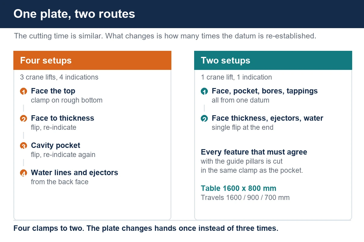
The old route was reasonable on paper. Face the first side. Flip, face the second side to thickness. Clamp on the second face and cut the cavity pocket. Flip again and drill the water lines and the ejector pattern from the back. Four clamps, four indications, and each one a chance to lose a few minutes of parallelism.
Three costs hide in that route. The first is handling: a 1500 kg plate needs the crane for every flip, and a crane is a shared resource in most toolrooms. The second is re-datuming: every clamp starts from a fresh edge find or a fresh probe cycle, and if the operator is rushed the second face is set from a different corner than the first. The third and worst is the interruption: a plate that leaves the table to wait for the crane is a plate that can be bumped, and a bumped plate is a re-cut.
None of these show up in a quote. They show up in the delivery date.
What we changed
The proposal was not to machine the plate faster. It was to machine it in fewer clamps on a machine whose table could hold the whole part and still have travel left over.
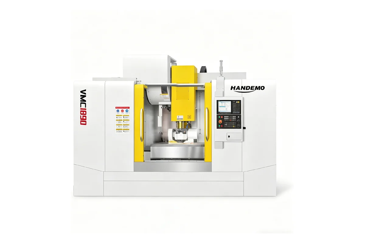
The plate went onto a VMC1690, whose table is 1600 x 800 mm with a 1,500 kg rating and travels of 1600 / 900 / 700 mm. The table size matters because the plate sits fully supported instead of overhanging, and the travels matter because the spindle can reach the far corner of the pocket without the fixture being stepped around. The BT50-190 spindle with 6000 rpm covers both the roughing of a 900 x 500 pocket and the smaller tools for water lines and clamp holes on the same machine.
The new sequence is two setups:
- Setup one: clamp on the rough bottom face with the plate supported on parallels or a sub-plate, face the top, rough the cavity pocket, finish the pocket walls and floor, bore the two guide pillar holes, drill and tap the clamp pattern, and drill the water line entries from the top.
- Setup two: flip once, face to thickness, cut the ejector pattern and the return pin holes, and break through the water lines from the back.
Two clamps instead of four. One crane lift instead of three. And critically, every feature that has to agree with the guide pillars is cut in setup one, from one datum.
Clamping a plate without bowing it
A plate this size is a spring. Clamp it on four corners over a hollow and the middle lifts. Clamp it in the middle and the corners lift. Either way the face you cut is flat only while the clamps are on, and it springs when you release.
What worked here:
- Support the plate on six or eight adjustable pads, not four, and shim until a dial indicator shows the same reading at the centre and at the corners before any cut.
- Clamp over the support points, not between them. A clamp that pulls down where there is nothing underneath is a bent plate.
- Keep the clamp load modest and repeatable. Torque wrenches are not common in toolrooms, but a marked setting on a torque-limited clamp is enough to make batch two behave like batch one.
- Rough the pocket in steps and let the plate relax between passes, rather than taking one deep pass that stores stress and releases it later.
- Leave the finishing allowance on the pocket floor until the second face has been faced, so the final floor cut is made on a plate that has already moved.
The indicator work at the start takes twenty minutes. The alternative takes a scrapped plate.
Pockets, corners and tool reach
The cavity pocket on this plate was 900 x 500 mm and 90 mm deep. That depth is not extreme, but it is enough that the tool holder has to fit inside the pocket without the holder rubbing the wall on the way down. The rule we quote with is simple: the largest tool that clears the corner radius decides the roughing time, and the smallest tool that reaches the floor decides the finishing time.
A pocket with tight corner radii forces a smaller cutter, and a smaller cutter means more passes. If the design allows a larger corner radius, the pocket gets cheaper without any change to the machine. That conversation is worth having with the tool designer before the plate is cut, not after. The cutting side of pocket work is covered in more detail in our article on machining a mold cavity.
For the deep sections, a shorter gauge-length holder and a smaller step-down beat a long reach tool pushed to its limit. The plate does not care how fast the tool is moving if the wall has to be scraped afterwards.
Holes that have to agree across the stack
The guide pillar bores are the features that decide whether the stack assembles. They are bored, not drilled, and they are bored in the same setup as the cavity pocket so the relationship between the pocket and the pillars is set once.
The same logic applies to the return pins and the ejector pattern: cut them in the setup where the reference face is the one that will sit against the next plate, so the pattern is defined against the surface that matters. When the plates arrive at fitting, the pillars go in with a light press and the ejector plate slides without a file.
Water lines are the opposite case. They are drilled from whichever face is convenient, they cross at internal intersections, and they are plugged at the ends. What they need is a clean breakthrough and no burr at the crossing, because a burr inside a water line is a flow restriction nobody can see. Through-spindle coolant and a peck cycle on the deep ones handle most of it.
Why not a horizontal machine, or a gantry
Both were considered. A horizontal machining center is the right answer for a box-shaped housing with bores on four sides, because the table indexes and the part stays put. A mould plate is not that shape. It is a wide, flat part with work on two parallel faces, and the work is easier to reach from above. A horizontal machine would hold it on a tombstone and force the operator to reach around it.
A gantry machine would also do the job, and on plates above two metres it becomes the only sensible option. At 1600 mm the vertical machine still has the table and the travel, and it loads from the front with a crane instead of from the side. We keep that boundary in mind when quoting: the plate size decides the layout, not the brand preference.
For shops that run a mix of plates and housings, the choice is usually made by whichever family pays the bills, and the other family gets scheduled around it. Smaller plates and insert blocks often stay on a mid-size machine such as the VMC855D, because moving a 200 kg block to a large table wastes travel.
What the customer measured afterwards
The toolroom tracked three things over the first two months: crane lifts per plate, setups per plate, and the number of plates that needed rework at fitting. Lifts dropped from three to one. Setups dropped from four to two. Rework at fitting went to zero on the first eleven plates, which they put down to the guide pillar bores and the pocket now coming off the same datum.
They also gained something they had not asked for. Because the plate stayed on the table between the pocket and the drilling, the machine ran unattended through the night shift on the second setup, and the operator came in to a finished plate instead of a plate waiting for a flip.
What decides the quote on a plate job
When a plate enquiry arrives, four things change the price more than anything else:
- The finished thickness and the stock allowance. A plate roughed 5 mm oversize on each face is a different job from one flame-cut close to size.
- The pocket depth to corner radius ratio. This is what decides whether a 50 mm cutter or a 16 mm cutter does the roughing.
- The number of faces with work on them. Two faces is a two-setup job; four faces is a different machine and a different conversation.
- Whether the plates are quoted as a stack or as singles. A stack quoted together lets the pillar bores and the ejector pattern be planned as one datum chain.
Send the assembly drawing as well as the individual plates if you have it. The plate drawing tells us the size; the assembly tells us which holes have to agree. Drawings can go straight through our drawing upload page if you would rather not send them by email.
FAQ
Can a 1600 mm plate be machined on a standard vertical machining center?
Yes, provided the table is at least as long as the plate and the travels reach the far corners. A 1600 x 800 mm table with 1600 mm of X travel, such as the VMC1690, holds a plate of that size fully supported. Anything longer needs a gantry layout or a machine with a longer bed.
Do you machine the whole mould base or only the plates?
Both. Plates, guide pillars, bushings, ejector plates and the smaller inserts can come off the same floor, which keeps the datum chain inside one shop instead of split between suppliers.
How do you stop a large plate from bowing after the pocket is cut?
By roughing in steps, supporting the plate on more than four points, clamping over the supports, and leaving the pocket floor allowance until the second face has been faced. The plate will still move; the sequence makes the movement happen before the finishing cut instead of after it.
Is pre-hardened plate harder to machine than annealed plate?
It is slower per pass, and it punishes a light machine. The advantage is that the plate does not go through heat treatment afterwards, so there is no second setup after hardening and no distortion to chase. For most mould bases in this size range the trade is worth it.
What do you need to quote a plate job?
The plate drawings, the assembly drawing if the stack has to assemble, the material and hardness, the pocket depths and corner radii, and the batch size. If the plates are part of a stack, send the whole stack in one enquiry.
Contact Handemo CNC | Email: sales1@handemocnc.com | WhatsApp: +86 135 6320 3038