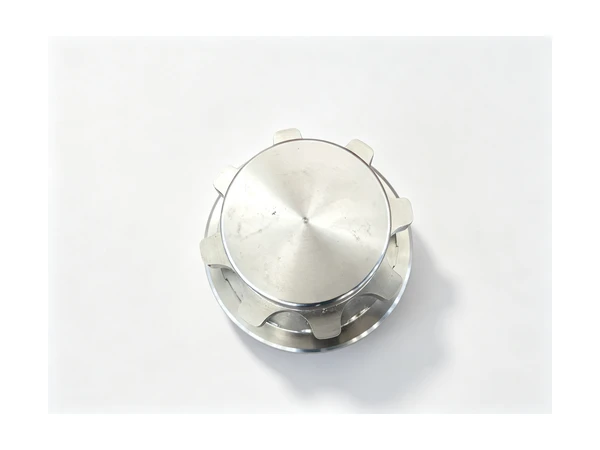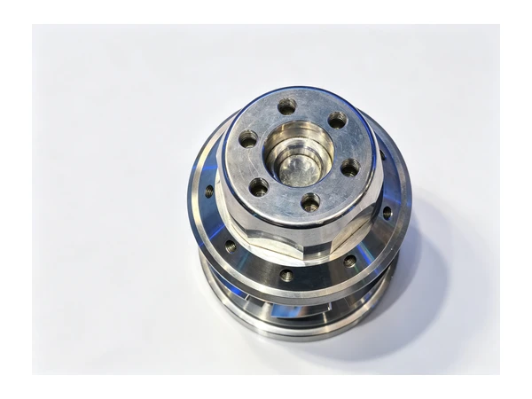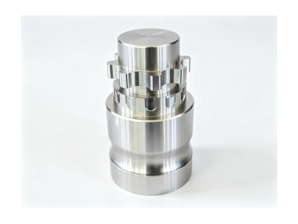
CNC Machining Coupling Hubs and Taper Lock Bushes
The complaint came with a short video: a pump drive running on a test bench, and a vibration you could hear over the motor. The coupling had already been replaced once. When the hubs came back to us, both bores measured what the drawing asked for. Both keyways were the right width. The flanges were flat. What was wrong was that on one hub the flange face and the bore did not share a centre, and on the other the jaw teeth had been cut from the flange face rather than from the bore. Nothing on a bench gauge would have caught either one.
A coupling hub is a small part with an awkward job. It does not carry a load like a gear or a shaft does, and it is not interesting to look at, so it gets quoted like a bushing with a flange on it. Then it goes into an assembly where its whole purpose is to make two rotating parts behave as one, and any disagreement between the bore and the outside of the hub shows up as noise, as wear on the bearing next door, and as a second trip back to the supplier. This is the family of parts we get asked about most often after shafts.
What follows is how we plan a coupling hub or a taper lock bush here: what the part has to do, why the bore is the only datum that matters, how the teeth and jaws are cut, and which machine ends up doing the work. It sits with the rest of our machining solutions notes, where each part family is written up the same way.
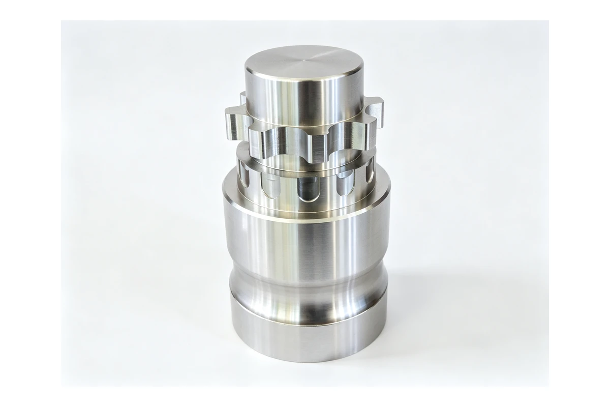
What a coupling hub actually has to do
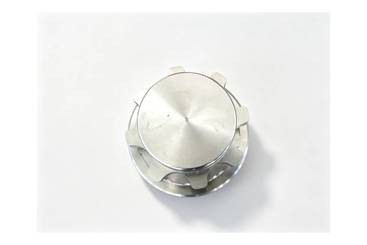
Two shafts on the same centreline, joined end to end. In the simplest case the two hubs bolt face to face and the joint is rigid. In most real cases the maker of the machine assumes the two shafts will never be perfectly in line, so the coupling is built to absorb a little of that: a rubber or polyurethane spider between two sets of teeth, a crown on the outside of a gear tooth pair, a stack of thin discs, or a pair of split tapered bushes that grip each shaft and are themselves bolted to a flange.
Whatever the style, the hub has the same list of features:
- A bore, usually with a keyway, that carries the torque and holds the hub on the shaft.
- A hub outside diameter, which is what the hub is turned from and often what a clamp or a guard clears.
- A working face: a flange with a bolt circle, a set of jaw teeth, a set of gear teeth, or a taper.
- One or two shoulders or faces that locate the part axially on the shaft.
- Often a balance feature, because the assembly turns fast and the hub is not symmetric after the keyway is cut.
Put in one sentence: the bore defines the axis, and every other feature on the hub has to be true to that bore. That is the whole job. A hub whose flange is flat but eccentric to its bore will pass inspection and still shake the machine it is fitted to, because the flange is what the second shaft is bolted to.
This is the same logic as the bushings, sleeves and rings we machine by the thousand, and it is why hubs are a workholding question rather than a measuring question. If you want the background on how a round part is held while its bore and its outside are brought into agreement, that article covers it.
The styles that land on the floor
Four families come through most often, and they are different jobs.
Rigid flanged hubs
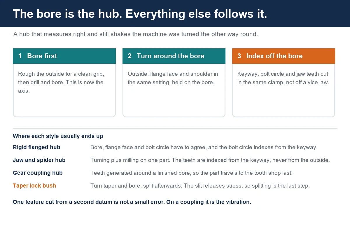
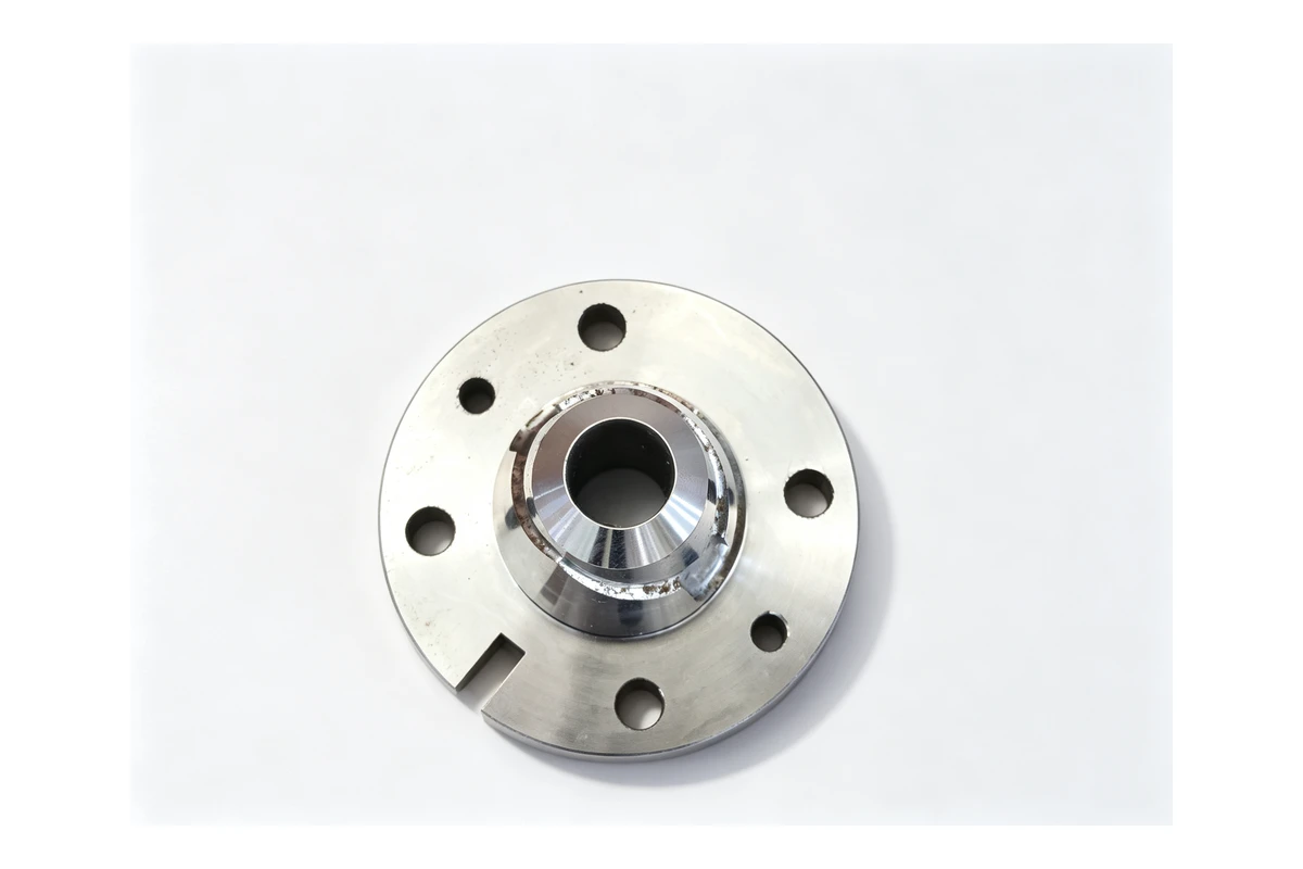
Two hubs and sometimes a spacer tube between them, bolted by a circle of holes in the flange. The part is essentially a short sleeve with a flange. The bore, the flange face and the bolt circle are the three features that have to agree, and the bolt circle has to be indexed from the keyway if the two halves are going to line up on the shafts in the direction the drawing intends. A rigid hub is the easiest of the four to plan and the least forgiving when it is wrong, because there is nothing in the joint to take up an error.
Jaw and spider hubs
Two identical hubs, each with a ring of projecting teeth on the face, with a moulded spider sitting between them so the teeth drive through the spider rather than against each other. The teeth are what the buyer inspects: the number of them, their width, the radius at the root, and how the whole set sits relative to the bore and the keyway. A jaw hub is a turning job and a milling job in one part, because the teeth are almost always cut after the body is turned, and the index they are cut from is the keyway, not the outside diameter.
Gear coupling hubs
Instead of jaws, the hub carries a ring of external, crowned teeth that mesh with a sleeve, and the crown is what lets the two shafts sit a little out of line. The teeth are cut on a gear machine or on a machining centre with a form tool, and the assembly is usually supplied as a pair with a common sleeve. What we are asked for here is the bore, the keyway, the shoulder faces and the blank with the teeth pre-cut or with the tooth circle left for the tooth shop, depending on the customer's split of work.
Taper lock bushes and hub pairs
A plain hub with a straight bore, plus a separate split bush with a matching taper on its outside. The bush grips the shaft, the hub is drawn onto the taper by the bolts, and the friction does the driving. The bore of the bush is where the shaft sits, but the match between the bush taper and the hub taper is what holds the assembly together, so these two parts are made as a pair or replaced as a pair.
Materials, and what each one does to the plan
Cast iron is still the default for a large hub or a taper lock hub body. It damps, it comes in volume cheap, and a GG25 casting leaves enough stock to clean up. The complication is that a raw casting has no round surface to indicate from, so the first operation is usually to grip the rough outside, face one side and establish the bore, and only then to turn the outside around that bore. Castings also arrive with hard patches, and a hard patch in an interrupted cut is what breaks an insert halfway through a finishing pass.
Medium carbon steel, 1045 being the usual grade, is what we see for steel hubs, spacers and flange plates. It turns cleanly, it takes a keyway without argument, and it is dimensionally calm. A flame or laser cut blank has a hard edge, so the first pass has to get underneath it rather than through it.
Alloy steel such as 4140 appears where the hub is also a drive part and the bore carries a real load. It is tougher than 1045, it will work harden if the tool rubs instead of cutting, and it is normally supplied pre-hardened, so the finishing passes are lighter and the insert grade matters more than the speed.
Aluminium shows up on small hubs for light drives and on anything where rotating mass has to come down, which on a coupling is a real design reason rather than a cost reason. It machines fast enough that the limit is chip evacuation. Stainless appears on food, dairy and washdown equipment, and it moves more than steel when the part is a thin flange, which is why a stainless hub is usually planned with more finishing stock and a lighter grip than the same part in 1045.
There are two more conditions that change the route without changing the shape. A hub that is case hardened or nitrided after machining will move, so the bore and the keyway have to be finished or re-cut after heat treatment rather than before. A hub that is going into a fast assembly will be asked for balanced, and the practical way to get there is to cut the keyway and drill the bolt circle on the same index and to keep the two hubs of a pair as close to each other in weight as the drawing allows.
The bore comes first, and it stays the datum
Almost every coupling complaint we see can be traced to one decision: which feature was picked as the datum, and in what order the others were cut from it.
The route that works is boring to describe. Rough turn the outside to get a clean round surface, face the ends, drill and bore the hub bore, then turn the outside, the flange face and any shoulder around the finished bore in the same setting where the machine can reach them. If the part is short enough to hold in one operation, the bore and the outside come off the same clamping, and the relationship between them is set by the machine rather than by the operator. If the flange face and the outside cannot both be reached from the bore side, the second operation has to be set on the finished bore, with a mandrel, a collet or soft jaws bored in place, and never on the raw outside.
The failure case is easy to picture. Turn the outside first, because it is the biggest surface and the quickest to gauge. Then hold the turned outside in a three jaw chuck, and bore from the back. Whatever runout the chuck has, whatever the outside is out of round by, and whatever chip got trapped between a jaw and the surface is copied into the bore. The part looks right, the bore measures right, and the hub wobbles on the shaft.
The same rule covers the keyway. A keyway cut from a hub that was set on its outside will sit wherever the outside happened to be. A keyway cut from the bore, or better still in the same setting as the bore on a lathe with a Y axis and driven tools, sits where the drawing says it sits. That matters on a coupling because the keyway is what indexes one hub against the other through the shafts.
Cutting the teeth, the jaws and the slots
Everything past the turning falls into the same pattern: a feature indexed by angle, cut from the bore.
On a jaw hub the teeth are usually milled. There are two sensible ways to do it. The first is on a lathe with a Y axis, driven tools and a C axis, where the jaws are milled in the same clamping as the bore and the keyway, and the index comes off the spindle rather than off a fixture. The second is on a machining centre with a fourth axis or on a horizontal with a tombstone, where the parts are set on a mandrel or in a bored collet and the rotation is indexed from the keyway. Both work. What does not work is setting the hub on its outside diameter in a vice and indexing from a jaw, because then the teeth follow the vice and not the shaft.
Gear coupling teeth are cut on a hobbing or shaping machine after the body is turned, and the tooth shop normally wants a finished bore to hold on, because the tooth circle is generated around whatever the part is held by. This is the reason we would rather deliver a gear hub with the bore already finished and the teeth cut afterwards than the other way round, even though it means the part travels twice.
Slots, bolt circles and clamp splits come last, and they are all drilling and milling work that has to be indexed from the bore or from a keyway that was itself indexed from the bore. On a hub with a split clamp, the split is sawn or wire cut after machining, and the saw cut removes material, which is exactly what it is supposed to do: the bore closes on the shaft when the clamp bolt is tightened.
Taper lock bushes: the split is a feature, not a cleanup
A taper lock bush is a small sleeve with an external taper that matches the hub, an internal bore for the shaft, a keyway, and a single slit down one side with part of a second slit on the opposite side. The first slit lets the bush flex when the bolts pull it into the taper. The second slit is what allows the hub to be released again, because the two jacking bolts bear on a shoulder and push the bush back out.
The taper is the part that has to be right, and it has to be right as a pair with the hub. Turning a taper on a lathe is straightforward while the part is held on a mandrel or between centres with the angle set from the slide; turning it on a part that has just been split is not, because the slit releases the internal stresses that were holding the part round. So the sequence is always: turn the taper and the bore first, split afterwards. The bush then goes into the hub and the pair is checked together, not separately.
The bore of the bush is where the shaft actually sits, and it is deliberately a plain fit rather than a tight one, because the grip comes from the taper being drawn in rather than from the bore. What a buyer should send with the enquiry is the shaft size, the taper of the hub it has to match, the number and size of the bolts, and whether the pair is being supplied as a set or as a replacement.
Which machine ends up doing the work
There is no single answer, and the honest one is that the part decides.
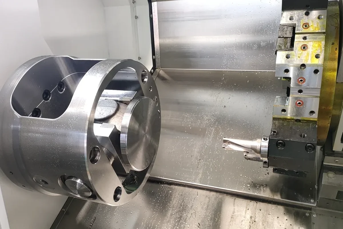
A turning job with a keyway and one bolt circle fits a lathe with a Y axis and driven tools, because then the bore, the outside, the keyway and the holes are one clamping and one setup list. For work up to about a 360 mm turning diameter with a 65 mm spindle bore and 50 mm bar capacity, a machine like the TCK50 slant bed lathe takes a hub in an 8 inch chuck and covers it with an 8 or 12 station turret. Larger hubs with a wider flange and a longer body go on the heavier TCK6350B, which has a 630 mm swing over the bed, a 96 mm spindle bore, an 85 mm bar capacity and an 18.5 kW spindle motor, and a 12 station turret that can carry the boring bars and the driven heads a hub job needs.
Where the drawing wants the jaws milled and the keyway cut with the same index, a lathe with a Y axis and a C axis makes the part in one clamping. The TCK6050Y is the machine we put on that work: 560 mm swing, 410 mm turning diameter, a 65 mm bore, Y travel of 50 mm either side of centre, and two bed lengths so the same turret covers a short hub and a longer spacer. For hubs that have to be machined on both ends, the bore finished first and then the opposite flange turned from it, a dual spindle mill turn machine such as the TCK6050SY takes the part in one machine instead of two: 67 mm and 56 mm spindle bores, 50 and 45 mm bar capacity, 18.5 kW on each spindle and a Y axis with 50 mm of travel.
Bolt circles, jaw teeth and clamp splits that are easier to mill than to turn belong on a vertical machining centre, and hub work is small enough that a mid size machine with a fourth axis is the usual answer. The VMC855 with its 1000 x 550 mm table, 800 x 550 x 550 mm travels, 600 kg table load and BT40 taper handles most of it, and the larger VMC1160 is there for the bigger flanges and for parts going on a four axis fixture or a tombstone.
When a hub family runs in batches rather than ones and twos, the setup time stops being a detail and becomes the job. That is the case where a horizontal with a pallet changer earns its place, because the second side of a hub can be cut while the first pallet is still being loaded, and the fixture stays on the machine rather than being rebuilt. Our notes on vertical and horizontal machining centres for multi face parts cover how that comparison usually comes out, and the guide to choosing a machine for box and housing work covers the fixture side of it.
When the batch has to repeat
One hub that runs true is a job. Five hundred that all run true is a process, and the difference is what drifts.
Three things move over a batch. The chuck jaws wear and the grip pressure changes, which matters on a thin walled hub where the part is round in the chuck and out of round when it comes out. The boring bar insert wears, so the bore creeps in one direction and every part that follows it follows the same creep. And the machine warms, so the first parts of a shift and the last parts of a shift are not cut under the same conditions unless the machine is left to settle or the offsets are checked at the start of the run.
The way to hold a hub batch together is to set the datum once and keep every operation on it. Finish the bore, and hold the part on the finished bore for the flange, the keyway and the bolt circle. Use soft jaws bored in place rather than hard jaws and a spider. Cut the keyway in the same machine if the machine can do it. Check the running of the hub on a mandrel rather than on the outside, because the outside is the surface the next operation will hold and it should not be the surface it is judged from. And if a pair of hubs is being made for one coupling, keep them together through the batch rather than finishing one and then the other.
What decides the quote on a hub job
Hub work is quoted from the drawing, and the price is mostly about how many clamps the part needs and how many features are indexed from one another.
- The bore and the keyway size, and whether the keyway is cut in the same setting.
- The number, the width and the form of the jaw or gear teeth, and whether the tooth circle is finished or left for a gear machine.
- The bolt circle: its diameter, the hole size and whether it is indexed from the keyway.
- The material and its condition, including whether it is a raw casting, a cut blank, or pre-hardened bar.
- Whether the part is heat treated, and in which order relative to the bore.
- Whether the hubs are supplied as pairs, with a spider, or as a hub and bush set that has to match.
- The batch size and whether the fixture is being made for the first time.
Send the drawing, the shaft size it goes on and the quantity, and the questions above are the ones we will come back with. If the part is a replacement for something that is already running in a machine, a photo of the old hub and the name on the coupling is usually worth more than a dimension we have to guess at.
Couplings, hubs and the shafts and housings they sit between are the kind of work we do every week, and they are covered in our case studies when a part deserves the space. If you have a hub that runs out, a coupling that will not settle, or a family of bushings that needs a repeatable route, send the drawing and we will come back with a plan and a price. You can send it through our drawing upload page. Contact Handemo CNC | Email: sales1@handemocnc.com | WhatsApp: +86 135 6320 3038
FAQ
Should the keyway be cut on the lathe or on a milling machine?
If the machine has driven tools and a Y axis, on the lathe in the same clamping as the bore, because the angular relationship between the keyway, the bolt circle and any second feature then comes off the machine instead of off a re-indication. If the hub has to go to a mill, set it on the finished bore, on a mandrel or in a bored collet, and index from the keyway rather than from the hub outside.
Can a coupling hub be bored from the outside diameter?
Only if the outside diameter is the feature the assembly depends on, which on a coupling it is not. The bore is where the shaft is, so the bore is the datum and the outside, the flange face, the teeth and the bolt circle all follow it. A hub turned outside first and bored from the turned surface will pass inspection and shake the machine.
Why does a taper lock bush have two slits?
The full length slit lets the bush close on the shaft when the bolts draw it into the taper. The shorter slit on the opposite side gives the bush somewhere to collapse when the jacking bolts push it back out, so the assembly can be taken apart without a puller and without damaging the hub.
Do hubs have to be balanced?
At low speed, no, and the keyway is the only thing that disturbs the symmetry enough to matter. At higher speeds, yes, and the practical way to get there is to cut the keyway and the bolt holes on the same index and to keep the weight of the two hubs of a pair as close as the drawing allows. If the assembly is going into a fan, a spindle or a pump drive, the drawing usually says so, and we would rather know before the parts are cut than after.
Can a hub be made from a casting instead of from bar?
Usually, yes, and for a large hub or a taper lock body a casting is the cheaper blank. The catch is the first operation: a raw casting has no round surface to indicate from, so the outside has to be gripped, one face cleaned up and the bore established before anything else can be turned true to it. Castings also carry hard patches, so the roughing pass has to get under the skin rather than through it.
What do you need to quote a coupling hub job?
The hub drawing with the material and its condition, the shaft size and the keyway, the mating half if the hubs are supplied as a pair, whether the teeth are finished here or pre-cut elsewhere, whether the part is heat treated and in which order, and the batch size. If it is a replacement, a photo of the part that failed and the coupling make and model save a round of questions.