
CNC Machines for Thin Wall Part Machining
Thin wall machining: how clamping force, cutting force and residual stress move a wall, and the sequence and workholding that keep it where it belongs.
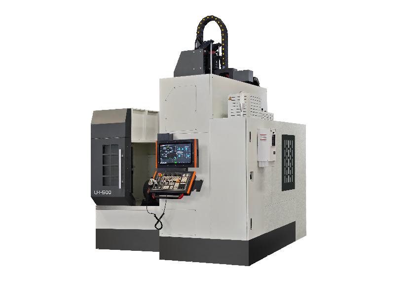
Machining Thin-Wall Parts
Thin-wall machining is not a matter of taking lighter cuts. A thin wall fails because the part is less stiff than the forces acting on it — clamping force, cutting force, and the residual stress that was in the material before it was cut. Cutting lighter reduces one of those three. The other two have to be designed out, and that is where most thin-wall jobs are won or lost.
This page covers the three forces that move a thin wall, the order of operations that keeps the wall where it belongs, how to hold a part without squeezing it out of shape, and what machine characteristics actually matter when the part is compliant.
The Three Forces That Move a Thin Wall
Clamping force
A thin wall in a vice or under chuck jaws is deflected before the tool touches it. The part is cut in a deflected state and springs back when released, so the wall that measured correctly under the clamp is wrong on the bench. This is the largest and most overlooked error in thin-wall work, and no amount of finishing passes corrects it — the error is created by the release, not by the cut.
Cutting force
A wall that is thin in the direction of the cut bends away from the tool and springs back into it, which produces chatter and a wall that is tapered and marked. The deflection is proportional to the force and inversely proportional to the wall's stiffness, so the same cut that is fine on a 5 mm wall will chatter on a 2 mm wall. Reducing radial engagement, using a sharper tool with a smaller nose radius, and cutting with the wall supported rather than free are the controls.
Residual stress in the material
Plate and extrusion carry internal stress from rolling or stretching, and removing material from one side unbalances it. The part bows after the first face is machined, and the second face is then cut on a part that is no longer flat. This is not a clamping error and it does not respond to lighter cuts — it responds to removing material evenly from both sides, or to stress-relieving the blank before machining.
The Order of Operations
Rough both sides before finishing either
Rough the first face, turn the part, rough the second, and only then finish. Roughing one side to finished thickness and then machining the other side guarantees that the stress release from the second side bows a part whose first side is already final. Leaving 1–2 mm on each side for the finish, and letting the part sit between roughing and finishing, lets the stress release happen while there is still material to remove.
Finish the wall in a sequence that keeps support
Where a part has internal pockets and external walls, machine the pockets first while the outside is still solid, then bring the outside down to thickness. The reverse order leaves the wall unsupported while the pocket is cut, and the wall moves into the pocket. The general rule is to remove material from the inside out, keeping the stiffest geometry for as long as possible.
Leave the wall attached as long as possible
A wall that is still connected to a thick base at one end is far stiffer than the same wall free-standing. Sequencing so the wall is machined while it is still attached, and parting it off last, is a standard technique on thin-wall parts and often removes the need for a special fixture.
How to Hold a Compliant Part
Vacuum and magnetic workholding
Vacuum holds a plate or a thin cover with a distributed force instead of concentrated jaw pressure, so the part is not deflected where it is held. For non-magnetic materials, vacuum is the default for thin plates; for magnetic materials, a magnetic chuck gives the same distributed support and is faster to load.
Soft jaws bored to the actual part
Where jaws are unavoidable, boring soft jaws to the part's finished diameter spreads the load over the full contact area and eliminates the three-point squeeze of a standard chuck. Low clamp pressure and a torque wrench on the chuck, rather than a hand-tight feel, make the clamping repeatable between operators.
Support from inside, or fill the cavity
A thin tube or a hollow part can be supported from the inside with a mandrel or an expanding plug, or filled with a low-melt alloy or a machinable wax that is melted out afterwards. This is slower per part but it is the technique that makes a wall thinner than the tool's reach machinable at all.
Plan for the spring-back in the tolerance
If the part deflects predictably under a known clamp pressure, the cut can be programmed to the deflected dimension so the released part lands on nominal. This requires measuring the part both clamped and free on the first few pieces, and it is worth doing on any part where the wall is the tolerance.
What Machine Characteristics Matter
Rigidity and damping over speed
On a compliant part, the machine's vibration behaviour matters more than its rapid speed. A machine with a heavily ribbed cast structure and a wide, rigid bed damps chatter that a lighter machine at the same cutting parameters will not. Where the part is the weak link, look at the structure's mass and the guideway type rather than the spindle's peak power.
Thermal stability
A thin wall heats quickly and expands, so a part cut over a long cycle will be measured differently at the start and the end of the run. A machine with a temperature-controlled spindle and a stable structure, plus finishing passes at consistent depth, keeps the wall dimension repeatable through the day.
Whether the machine can reach both sides
A part with thin walls on both faces needs to be machined from both sides, and either the part is turned around — with the release problem that implies — or the machine has the axes to reach both. This is where a mill-turn machine or a five-axis machine changes the process rather than just the cycle time.
Process Notes for Thin Walls
Measure after release, always
The only dimension that matters is the one measured with the part free. Measuring in the fixture is useful for controlling the cut, but it is not the acceptance measurement, and treating it as one is how a batch of parts passes inspection in the machine and fails at the customer.
Use climb milling on the finishing pass
Climb milling puts the chip load behind the tooth and pulls the wall toward the cutter rather than pushing it away, which on a thin wall produces a cleaner finish and less deflection. The same applies to a finishing pass on a thin rib.
Do not chase the tolerance with a spring pass
A spring pass on a deflected wall cuts where the wall is, not where it should be, and can make the error worse by removing material from the part's high side. Fix the deflection with support and sequence rather than with extra passes.
Related Guides
- CNC machining thin wall parts - the full process route
- Bearing housing machining - bore distortion after clamp release
- Flange and end cover machining - coning on thin discs
- Slant bed vs flat bed lathes - rigidity and damping compared
- CNC mill-turn machines - reaching both faces in one clamping
More Application Guides
Handemo builds machines for each of these part families. Each guide covers what the part demands from the machine and how the process is sequenced.
Discuss Your Thin-Wall Part
Send the drawing with the wall thickness, the material and its condition, the flatness callout and the batch size, and we will suggest the workholding and the sequence.
Request a Process Review