Large Flange Machining: Why a Ring Springs Back
A large flange looks like the easiest part on the shop floor. It is a ring. You face it, you bore it, you drill a circle of holes. There is no cavity, no thin web, no five-axis surfacing. Yet this is the family of parts where good shops lose arguments with customers, and the argument is almost never about the cut. It is about what happens in the thirty seconds after the chuck is opened.
A ring that measured flat while it was clamped can sit on a surface plate and rock. A bore that ran true under jaw pressure can close up when the pressure comes off. The part did not change; the load did. Everything below is about that gap between the shape you cut and the shape the customer receives, and about the choices in clamping, sequence and machine that close it.
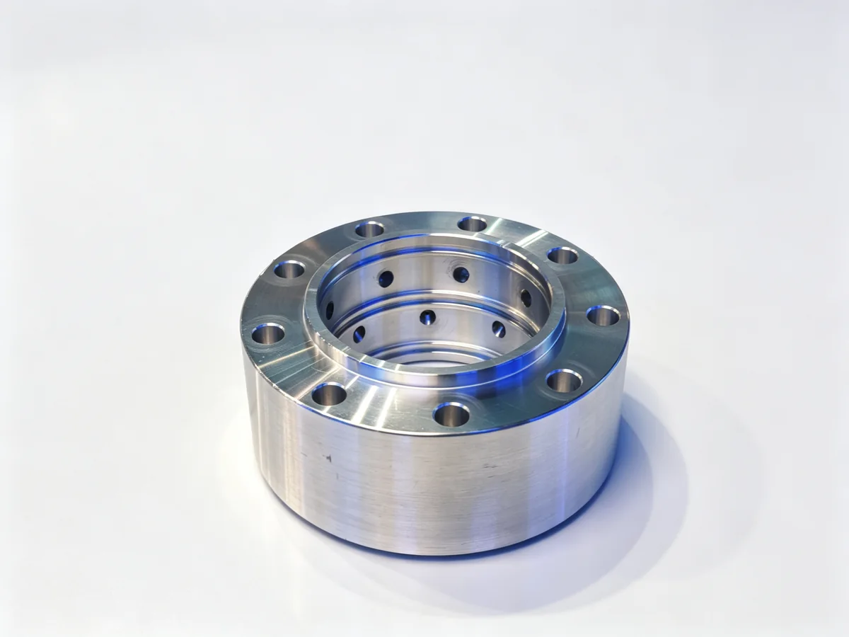
What Counts as a Large Flange
Large flange machining covers four families of part that behave differently under the tool, and it helps to know which one is on the table before choosing anything else.
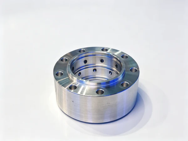
- Tower and pipe flanges. Rolled or forged rings, usually with a raised face, a bolt circle and a matching bolt pattern on the opposite flange. Diameters run from a few hundred millimetres to several metres. The face is the sealing surface, so flatness and the finish of that face carry the job.
- Slewing ring races. The inner and outer rings of a slewing bearing, with a groove or a raceway and a gear cut on one of them. Two rings that must match, and a raceway that has to be concentric with the mounting bore rather than with the outside diameter.
- Large coupling and shaft flanges. A flange on the end of a shaft, with a pilot spigot that has to sit concentric with the shaft axis. The bolt circle is secondary; the spigot is what centres the joint.
- Structural and machine frame rings. Weldments or flame-cut plate, often irregular in thickness, with machined pads rather than a full face. Here the job is not roundness but the relationship between pads that were welded in a fixture and then distorted by the weld.
Each one fails differently. A pipe flange that is not flat leaks at the gasket and everyone smells it. A slewing ring race that is not concentric with its mounting bore runs rough and wears a bearing out in a year. A coupling spigot that is off makes a shaft vibrate at a frequency nobody can find. All three trace back to the same question: what was the part allowed to do while it was being cut.
Why a Ring Changes Shape When You Let Go
Every clamping method applies force somewhere, and a ring is a spring. It is a closed loop of material with a relatively small radial stiffness, which means a modest radial push produces a measurable deflection, and that deflection is elastic. Cut the part while it is deflected and you have cut a shape that only exists under load.
The classic case is the three-jaw chuck. The scroll generates jaw force as a function of how far the jaws travel, so the force you apply to a 900 mm ring is not the force the chuck was designed around for a 200 mm bar. The ring goes slightly triangular at three points. You face it, and the face is flat while the ring is triangular. Open the jaws and the ring springs back to round, and the face now has three high spots where the jaws were and three low ones between them. On a gasket joint, that is a leak path. On a bearing seat, it is a rocking outer ring.
Four independent jaws are better because you can set each one to the same reading, but they do not solve the problem. Four points still pinch. The ring flattens between the jaws and bulges at them, and because the jaw positions are chosen by the operator rather than by the part, the error moves from job to job.
The method that avoids the problem is the one that does not push inward at all. A face plate with axial clamps holds the ring down against a faced surface and leaves it free to keep its own diameter. Radial freedom is the whole point: the part is located axially and driven by friction or by a drive dog, and nothing squeezes it. What you cut is what it will be when it is loose.

There is a second, less obvious source of the same effect: heat. A ring that has been rough turned holds a temperature gradient, and the outside cools before the inside. If you finish it hot, it shrinks as it cools and the finished bore is smaller than the one you measured. This is why the sequence below has a cooling gap in it, and why the gap matters more on a ring than on a solid part of the same mass.
Three Ways to Hold It, and What Each One Costs
Three-jaw scroll chuck
Fast, self-centring, and wrong for anything thin or large. It is the right choice for a heavy, thick ring where the wall is stiff enough that jaw force produces a deflection you cannot measure and the part is not going to move. On a 200 mm thick forged ring it is a fine answer. On a 25 mm wall rolled ring it is the reason the customer sends the part back.
Four independent jaws
The standard compromise on a horizontal or vertical lathe with a four-jaw. Each jaw is set against the part with a dial indicator, so the operator can equalise the load. It works, but it depends on the operator's patience, and it leaves four hard contact points that become four low spots on the finished diameter. On a part where the outside diameter is cosmetic, that is acceptable. On a raceway, it is not.
Face plate, axial clamps, or a purpose-built fixture
The method that matches the physics. The ring sits on a plate that has been faced true in place, and it is held by clamps that push down rather than in. Three or six clamps, each with a soft pad, each tightened to a feeler-checked gap. Radial location comes from three adjustable stops that touch without loading. This takes longer to set up and it is the only one of the three that gives a part whose loose shape matches its clamped shape.
For production, the same idea becomes a dedicated fixture: a plate with a register, three or six swing clamps, and a marked position for each clamp so the next operation puts the part back in the same place. The fixture is not a luxury on a ring; it is the tool that makes the second operation possible.
Where the Error Actually Shows Up
Four numbers get measured on a flange, and three of them are usually measured wrong. The distinction matters because each one points at a different culprit.
| What you measure | How it is taken | What it tells you |
|---|---|---|
| Face runout, clamped | Indicator on the face, part still in the chuck | About the setup, not about the part |
| Face runout, free | Part loose on a plate, three points, no jaw load | About the part, and the only reading the customer will repeat |
| Flatness across the face | Straight edge and feeler, or a height gauge on a plate | What the gasket actually sees |
| Squareness of face to bore | Face indicated while the bore is the reference, or the reverse | What the bearing or the mating spigot sees |
The trap is the first row. A part indicated in the chuck will always look better than the same part on a plate, because the chuck is holding it in the shape you cut. Signing off on a clamped reading is how a shop ships a part it believes is good and gets it back. The second row is the honest one, and it is the one to put on the inspection sheet.
There is a third reading that gets skipped: the outside diameter. On a ring held in jaws, the outside is measured between jaw positions, so it reads smaller than it is at the jaws. If the customer checks the diameter with a tape or a large micrometer at a random point, two people can disagree about the same part without either of them being careless.
The Order of Operations
The sequence below is for a ring that has to end up flat, round and concentric, in that order of difficulty. It is written for a lathe with a face plate, and it assumes the ring arrives as a rolled or flame-cut blank with some scale on it.
- Rough both faces and the outside, leave stock, then let it cool. Roughing puts heat in and relieves residual stress from rolling or flame cutting. The cooling gap is not a delay, it is an operation, and skipping it is why the finish cut moves.
- Face the plate in place and mark the clamp positions. The plate is the reference for everything after this. If it is not true, no amount of care on the part helps.
- Seat the ring on three points and check with a feeler. A ring that rocks on the plate will be cut in a twisted shape and will rock again when it is delivered. Find the rock now, not after the finish cut.
- Clamp axially, lightly, and check that the ring has not moved. Enough load to drive the cut, not enough to bend the part. If the ring creeps, the problem is drive, not clamp force, and the answer is a drive dog rather than a tighter clamp.
- Semi-finish the face, release, re-seat, and check again. This is the step that separates shops that hold flanges from shops that fight them. Releasing lets the part take its own shape, and re-seating shows you whether it changed.
- Finish the face and the bore in the same clamp. Squareness between the face and the bore is created by the clamp, not by the tool. Two setups mean two chances to lose it.
- Drill and ream the bolt circle before unclamping. The holes are the last chance to be wrong. Position them from the bore, not from the outside diameter, and drill them while the part is still located by the same fixture.
- Mark the clamp positions on the part. The next operation, whether it is the opposite face, a groove or a gear, will want the same load in the same places. A marker pen is cheaper than a fixture and almost as effective.
On a ring with a groove or a raceway, a ninth step belongs between six and seven: cut the groove in the same clamp as the face and the bore, because the groove's position relative to the mounting face is what the bearing feels. Moving the part to another machine for the groove is a decision that has to be paid for somewhere, and it is usually paid for at the customer's assembly line.
Materials and What Each One Does to the Cut
Rolled carbon steel: S355, Q355, A105
The common case. Rolled rings carry residual stress from the rolling and from the cooling of a thick section, and flame-cut plate carries a harder layer at the cut edge plus stress from the thermal cycle. Both release stress when you remove material, which is why the roughing pass is followed by a pause. The cut itself is forgiving: a coated carbide insert at a moderate speed will run all day, and the risk is not the tool but the scale, which is abrasive and will take the edge off an insert in the first metre if you let it rub.
42CrMo, 4140 and other quenched and tempered grades
These arrive either pre-hardened or soft and are hardened after machining. The second case is the one that catches people. If the ring is to be quenched and tempered after turning, the finish cut before heat treatment is a semi-finish, and the distortion from quenching has to be removed afterwards. That means either leaving enough stock for a post-heat-treatment pass or accepting that the part will be straightened and re-cut. A flange that is quenched as a thin ring will move, and the movement is not uniform around the circumference, so the correction pass is a real operation and should be in the quote.
Stainless and duplex
Stainless rings for chemical and food service are usually turned from plate or forged rings, and the problem is work hardening plus chip control. A duplex flange is harder again: the material work hardens quickly, the chips are tough, and a light pass that rubs rather than cuts will harden the surface you are about to finish. The rule is to stay in the cut, keep the feed up, and never let the tool dwell. Coolant has to reach the edge, not the chip.
If the flange is stainless and will be welded to a stainless pipe, cutting fluid contamination becomes a welding problem. That is worth agreeing with the customer before the first cut rather than after the weld fails a dye penetrant check.
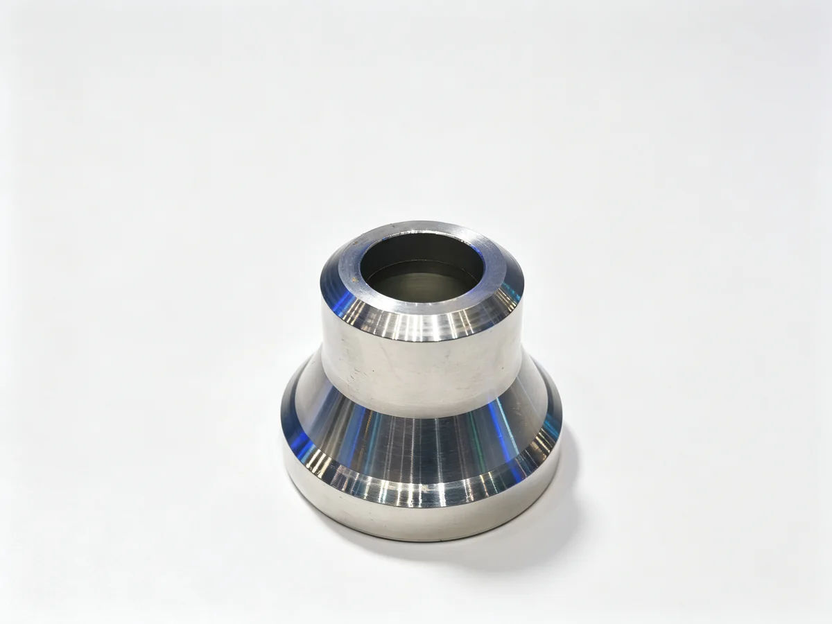
Drilling the Bolt Circle
The bolt circle is where a flange job either runs smoothly or eats a shift. Three things decide it.
The first is the reference. Holes positioned from the outside diameter inherit every error in the outside diameter, including the error you created by holding the part in jaws. Holes positioned from the bore inherit the bore, which is the surface the mating part will use. Position from the bore, and if the drawing shows the circle dimensioned from the outside, ask before you assume.
The second is the machine. On a vertical lathe with a live tool or a powered turret, the bolt circle can be drilled in the same clamp as the face, which is the cheapest correct answer. On a horizontal lathe the part usually goes to a machining centre, and the moment it moves, the clamp changes and the part is released and re-held. That is the point where a flat face becomes a slightly less flat face. If the holes are numerous and the flange is large, a radial drill or a machining centre with a rotary table is often the practical route, and the fixture has to be designed so the part sits the same way it sat on the lathe.
The third is the pattern itself. A bolt circle that is drilled with a dividing head or an indexer accumulates error in one direction if the index is set from one starting point. Indexing all the way around back to the start, and checking the closure, catches the accumulation before the part is finished. On a circle with an odd number of holes, there is no opposite hole to check against, so the closure check is the only one available.
Which Machine Gets the Ring
Size decides the family, and the family decides the machine. The four answers below cover most of what arrives at a shop that does general subcontract work.
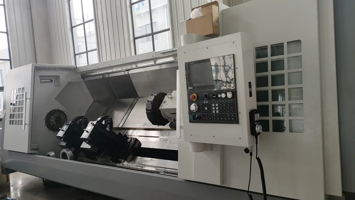
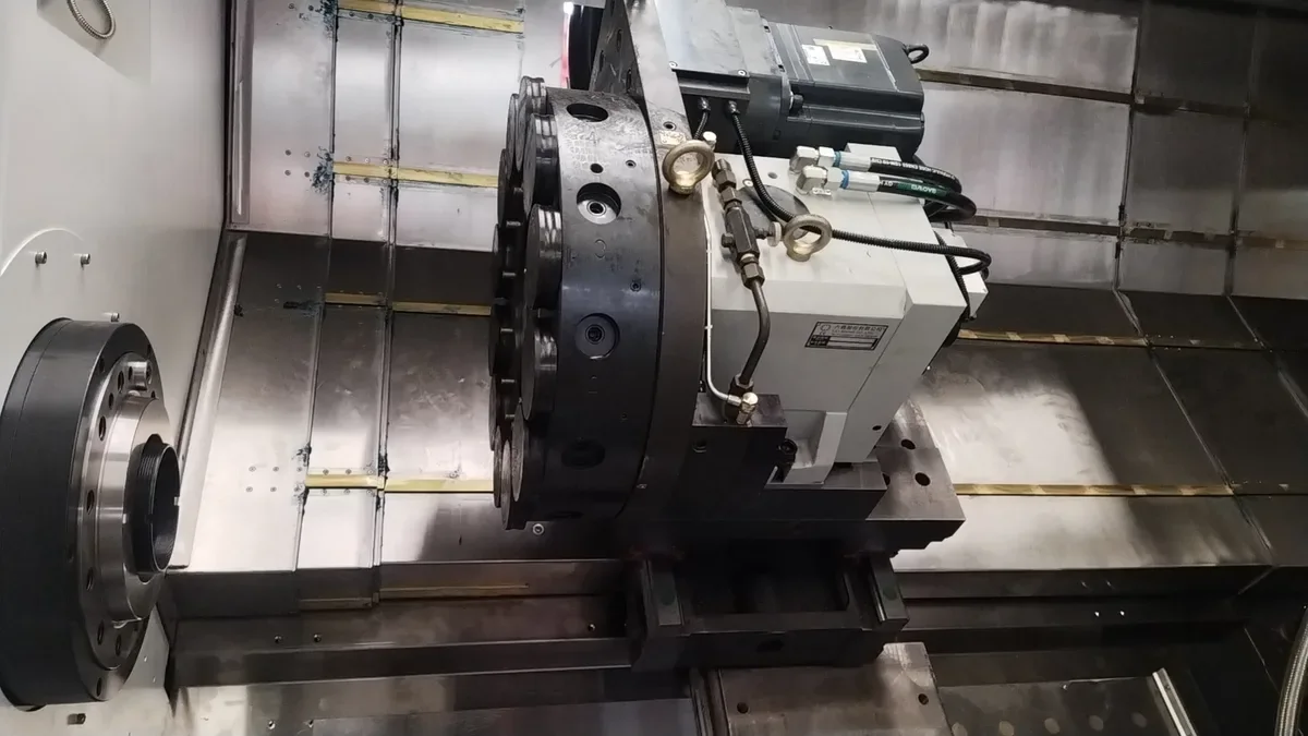
Rings up to about 800 mm and 200 mm of bar. A large-bore slant bed lathe with a big spindle through-hole is the efficient answer, because a ring that can pass through the bore can also be held in a chuck with a large through-hole for shaft work, and one machine covers both. The QK1322 mill-turn machine is built around that idea: a 240 mm spindle bore, 220 mm bar capacity, 800 mm maximum turning diameter and 1,600 mm of Z travel, with the ability to cut threads and mill on the same part.
Rings up to about 800 mm on a long bed. Where the ring is part of a longer assembly, or the part is a flange on a shaft rather than a free ring, the bed length matters more than the swing. The TCK80B-1500 carries a 120 mm spindle bore and a 1,500 mm cutting length, which puts a flange and its shaft in one clamp.
Heavy rings and short parts. A ring with a thick wall and a short face is a weight problem, not a length problem. The TCK6350B is the machine in the range that is bought for its cast iron rather than its swing: a 96 mm bore, 630 mm over the bed, and the mass to take an interrupted cut on a flame-cut edge without the whole machine ringing.
Small rings, pads and bolt-on details. A ring that has machined pads rather than a full face, or a flange with a keyway and a set of tapped holes on a bolt pattern, is often faster on a vertical machining centre with a fourth axis or a trunnion. The VMC1160, with a 1200 × 600 table and an 800 kg table load, will take a ring on a fixture and do the drilling, tapping and keyway in one clamp. On a bigger frame with pads on several faces, the answer shifts to a horizontal machining centre where the pallet does the indexing and the part keeps one clamp through four faces.
The honest summary is that a ring wants a lathe with a face plate and, if the bolt circle is large, a second machine with a rotary table. Trying to do everything on one machine is how shops end up with a fixture that takes four hours to set and a part that is still not flat. Most of the cost in cnc machining large flanges sits in the fixture and the second clamp, not in the cutting time.
What to Put on the Drawing When You Send It
Most flange jobs that go wrong were quoted from an incomplete drawing, not machined badly. Six items close the gap.
- The datum, stated as a surface rather than implied by the dimension chain. Which face is the mounting face, and which bore is the locating bore. If the drawing dimensions the bolt circle from the outside diameter, say so explicitly.
- The condition of the blank: rolled ring, forged ring, flame-cut plate, or weldment. Each has a different stress history and a different amount of stock needed.
- Whether the part is heat treated after machining, and if so, whether the finish cut happens before or after. This single answer changes the process plan.
- The flatness requirement of the sealing face and whether it is measured loose or clamped. A number without a method is not a requirement.
- The bolt circle reference and what each hole is for: drilled clearance, reamed for a dowel, or tapped, since a dowel hole changes the process.
- The quantity and the repeat interval. A one-off and a monthly batch of twenty want different fixtures, and the fixture is a real cost that belongs in the price rather than in a surprise later.
If the part is a replacement for something already in service, the most useful thing you can send is a photo of the worn part next to the drawing, or the mating part. Flanges that have been in service for years are rarely still at their drawing dimensions, and the difference tells you what the joint actually needs.
FAQ
Why does my flange rock on a surface plate after machining?
Because it was cut while it was held in a shape that was not its own. Jaw force, clamp force at four points, or heat from roughing all bend or distort a ring, and the cut takes the distorted shape. When the load comes off, the part returns to its natural shape and the face is no longer flat. The fix is axial clamping on a faced plate with the part free to keep its diameter, and a release-and-re-seat step before the finish cut.
Can I hold a large ring in a three-jaw chuck if I take light cuts?
Light cuts reduce the cutting force but not the clamping force, and it is the clamping force that bends the ring. A light finish cut in a three-jaw chuck produces a face that is flat only while the jaws are closed. If the wall is thick enough that the deflection is below what anyone will measure, the chuck is fine. If it is not, no depth of cut will save it.
Should the bolt circle be drilled on the lathe or on a machining centre?
On the lathe if the machine has a live tool or a powered turret, because the part stays in one clamp and the holes inherit the bore. On a machining centre if the circle is large, the hole count is high, or the flange carries pads and keyways that need a milling spindle anyway. What to avoid is moving the part for the holes and then re-cutting the face, because the second clamp is a new source of error.
What causes a flange to be round on the outside and out of round in the bore?
Almost always a chuck or a fixture that located on the outside diameter. The outside is held round by the jaws, so it measures well, while the bore is cut in a part that is being squeezed. The reading you get is the shape of the constraint, not the shape of the part. Locate on a faced surface and a bore, or on three points with radial freedom.
How much stock should be left for heat treatment?
It depends on the section and the quench, and it should be agreed with the heat treater rather than guessed. As a rule the allowance has to cover distortion plus the decarburised layer plus enough material for a clean-up pass on both the face and the bore. On thin rings the distortion is not uniform around the circumference, so a single radial allowance is optimistic.
Can a weldment be machined to the same flatness as a rolled ring?
Only after stress relief. A welded ring carries stress from every weld, and machining one face releases it and moves the other. The sequence is weld, stress relieve, rough machine, and then finish, with the part free to move between roughing and finishing. Machining a weldment without stress relief produces a part that is flat in the shop and moves in service.
Talk to Us About Your Flange
If you are sourcing large flanges, slewing ring races or heavy rings, send the drawing and tell us the blank condition and the batch size. The four details that change the answer are the outside diameter, the wall thickness, whether the bolt circle is dimensioned from the bore or the outside, and whether the part is heat treated after machining. With those four we can tell you whether the job belongs on a large-bore lathe, on a heavy slant bed with a face plate, or on a machining centre with a fixture.
Write to sales1@handemocnc.com or message us on WhatsApp at +86 135 6320 3038. PDF and STEP drawings are both fine, and a photo of the worn part is welcome. If you are still working out the process, the guide to flange bearing housing machining covers the housing side of the same joint, the article on thin wall machining goes deeper into deflection under clamp load, and the split bearing housing case study shows what a one-clamp strategy looks like when the part is a housing rather than a ring.
Related reading: bushings, sleeves and rings, impeller machining, and the full machining solutions index. If you would rather send a drawing straight away, the drawing upload page takes PDF, STEP and photos.