CNC Machining Impellers: Process and Machines
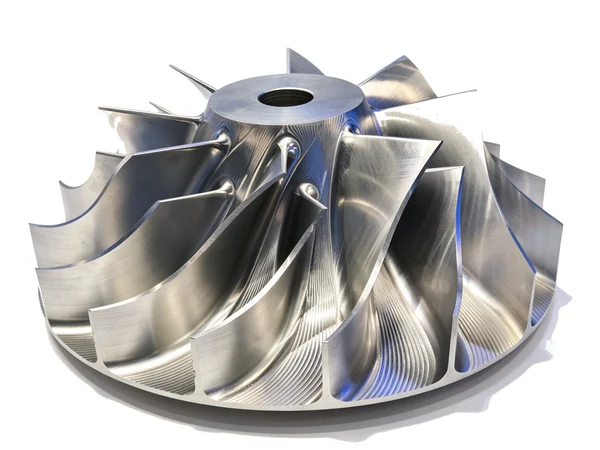
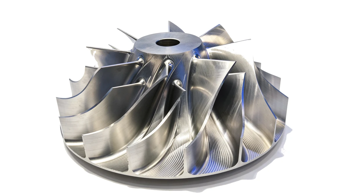
There is a particular kind of enquiry that arrives as one photograph and one sentence: this is the impeller, can you machine it? The photograph is almost always taken on a bench, in daylight, from slightly above, and it shows a part that looks like a metal flower with the blades fanned out. The sentence is almost always about the finish, or about a blade that keeps moving when it is measured.
Impellers are one of those jobs where the shape is not the hard part. A blade is, after all, just a curve with a thickness. The hard part is that every blade is thin, unsupported at the tip, and connected to a hub that has to be cut in the same setup. The impeller in the photograph below came off a machine in our own workshop after the finishing pass, and the reason it is worth showing is that nothing on it was polished afterwards. The flow surfaces are as they were cut.
Why an Impeller Is Not Just a Milled Part
Look at what the cutter actually has to do. As the tool works down a blade, the cut is interrupted twice per pass, the tool sticks out far enough to sing, and the wall behind it is thin enough to deflect away instead of being cut. Then it moves to the next blade, and the next, until it comes back around. By the time the last blade is done, the part has been loaded and unloaded by the cutting forces many times.
Add the fact that the blades close up toward the hub, so the space between them narrows exactly where the tool has the least room, and you have a part where the sequence matters more than the cutting data. Three things decide whether the job runs smoothly:
- Whether the blades are rough and finished in separate passes, or all in one go
- Whether the hub, the blades and the back face share one datum or three
- Whether anything is checked for balance before the finishing cut, or only after
Nothing on that list is exotic. It is the same discipline as any thin-wall work, applied to a shape that is thin in every direction at once.
The Blank Decides Half the Job
Impellers in the sizes we usually see arrive in one of four forms, and each one sets a different starting point.
A casting. The blades come out of the foundry as a near-net shape, so the machine is not removing a disc, it is cleaning up something that is already roughly right. That is the cheapest route on material and the most demanding on the first operation, because the casting arrives with its own stress and with a skin that has to come off evenly. Castings are usually roughed all over, then left to rest before anything is finished.
A forging. Denser and more predictable than a casting, and the natural choice for impellers that will run fast or see load. Forged blanks normally need a heavier first pass, and the forging flash has to be cleared before the blade roots can be cut cleanly.
Solid bar or a plate. The blank is a solid disc or a stepped round, and everything between the blades comes out as chips. This is the route for prototypes, for small batches, and for impellers where the customer wants one material throughout. It is the most expensive on machining time, and it is often the fastest way to a first article because there is nothing to prepare.
A near-net blank from another process. Sometimes the disc arrives with the backbone of the blades already formed, and the machine is doing the flow surfaces and the roots. That is a good arrangement, provided the pre-formed stock is even. Uneven stock on a thin blade is worse than no blade at all, because the tool is now cutting an interrupted depth.
Whatever the blank, one rule holds: the first operation should remove material evenly from both the hub and the outside, so the part releases its own movement on the machine rather than in the inspection room.
One Datum, Established First, Kept Throughout
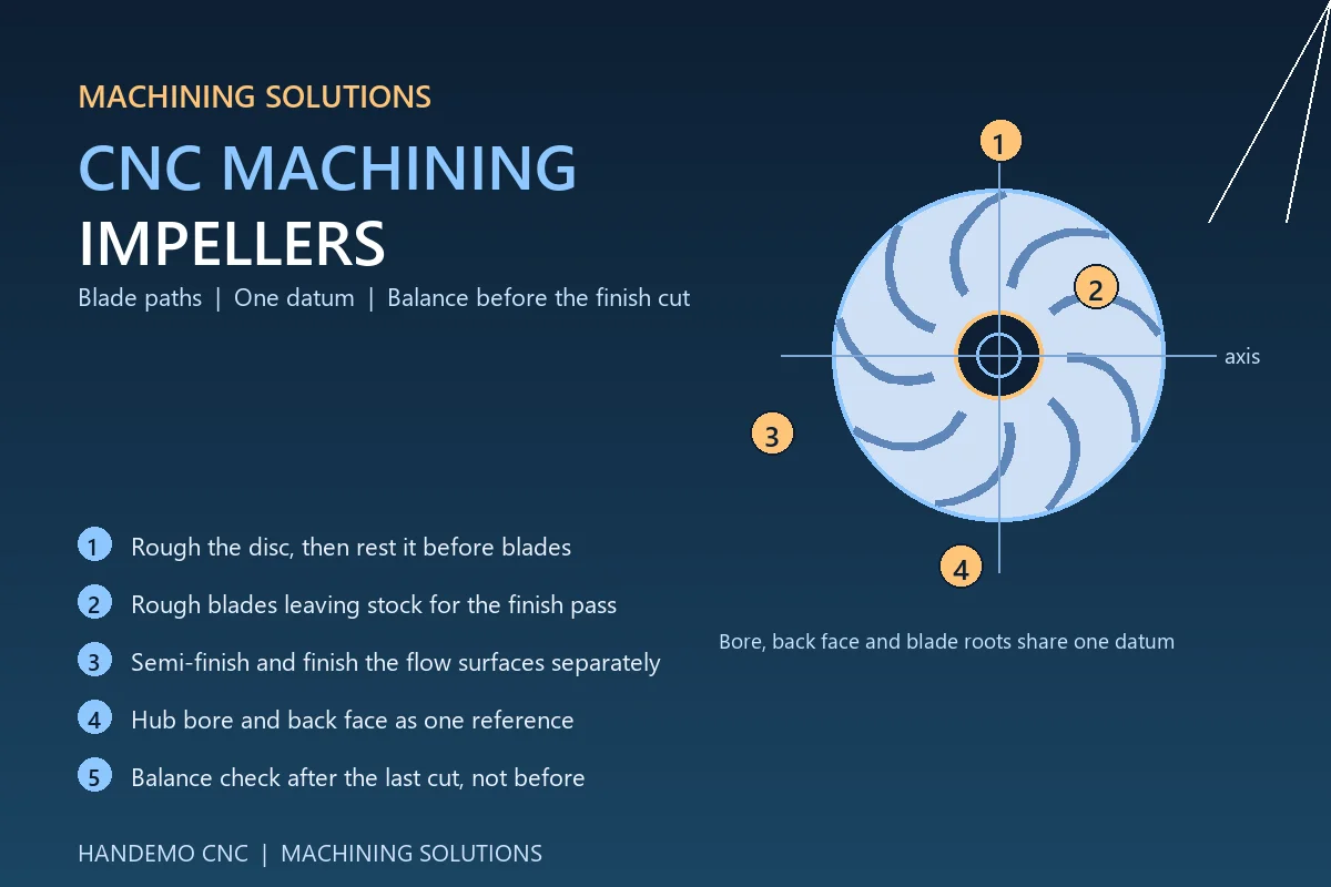
The impeller will be measured from its bore and its back face. That is the reference the customer uses, so it should be the reference the machine uses from the first cut. Boring the hub and facing the back seat in one setup gives the whole job a spine, and every blade, root and flow surface is then cut relative to it.
Where that reference is established on a second setup, part of it goes back to the jaws, and the runout that appears at the blade tips is quietly built in before any blade is cut. Where it is established once, the rest of the job is a matter of tool reach and pass planning.
Holding a Bladed Part
The workholding question is unusual here, because the outside of the part is the feature that must not be touched. Blades do not tolerate jaw pressure, and there is no continuous surface to clamp against. In practice the choices are:
- A dedicated fixture on the back face or the hub flange, with the part seated on the datum face and pulled down by bolts placed in the central region. The blades stay free.
- A stub mandrel or expanding collet in the hub bore, with the back face resting against the fixture, for parts small enough that the bore can carry the load.
- A soft, contoured cradle that supports the blade roots from below while the flow surfaces are cut, taking the cutting force out of the blade itself.
Whichever is used, the fixture is worth more than any insert choice. A blade that deflects under load will be cut to a different shape in the morning than in the afternoon, and no operator can see that happening.
Roughing the Blades
Blades are roughed in their own pass, deliberately leaving stock for the finish, and the goals of that pass are unspectacular: remove the bulk, keep the tool loaded, and do not damage the blade root.
Two habits matter. The first is a shorter, stiffer tool for the roughing pass than the finish will need. The blade faces will be reached later by a tool with more reach, but there is no reason to take a long tool through heavy metal. The second is to work down the blade from the tip toward the root, so that the stiffness of the part increases as the pass goes on and the material being removed supports the blade while it is still there.
Chatter in this pass is normal and can be managed with depth of cut and feed. Faint chatter marks left in the roughing pass are not a failure, provided the finish pass has enough stock to remove them. What is a failure is a roughing pass that leaves the blade root thin, because the root is what holds the blade against everything that happens afterwards. Where the blade meets the hub, the fillet should be left generous through roughing and only brought to its final shape once, at the end.
Finishing the Flow Surfaces
The flow surfaces are what the customer sees and what the air or fluid touches. They are also where a shop's process shows, because a badly planned finish pass leaves the sort of marks that no amount of polishing will remove consistently.
The sequence that works in our experience is three steps, not two:
Semi-finish first. A parallel pass with a modest step-over, run at a steady tool pressure, to bring the blades within a light, uniform stock of final. This is the pass that finds any remaining unevenness from the blank or the roughing, and it is much cheaper to fix it here than after finishing.
Finish without stopping. On the flow surfaces the aim is a constant engagement, so that the tool leaves a consistent surface from root to tip. Where the surface is cut, then paused, then cut again — as happens when a tool lifts and plunges between blades — the pause is visible in the finish. Keeping the tool down through a blade and lifting only in the open space between blades evens the whole surface out.
Leave the critical edge for last. The trailing edge of a blade is thin, and any finishing pass near it pushes material rather than cutting it. On impellers where that edge matters, doing the edge after the flow surfaces, with a light pass and a sharp tool, keeps the blade from being rolled over at the end of the job.
On the hub and the back face a standard turning or milling routine is enough. Those are solid features, they do not deflect, and they are usually the first surfaces that can be signed off.
Where the Machine Comes In
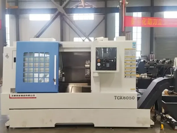
Bladed work is the clearest case for a machine that can reach the part without re-clamping it. Every additional setup is another chance for the blade tips to move relative to the hub, and that movement is exactly the error the customer measures.
For impellers that are largely rotational with shallow blades, a vertical machining center with the part on a rotary table will do the work, and a rigid frame such as the VMC1160 gives the tool reach without the frame moving under the interrupted cut.
Where the blades are deep, twisted and closed toward the hub, the tool has to approach from changing angles, and that is where a five-axis machining center earns its place. With the part swinging under a driven spindle, the blade surfaces are cut from a series of angles rather than from one, so the tool stays on the surface instead of reaching into it at a steep angle and rubbing. A machine such as the U400 suits smaller impellers and bladed discs that sit well within its table, and the TMC630 covers the larger size band, with the part carried on a trunnion table so the whole blade can be presented to the tool.
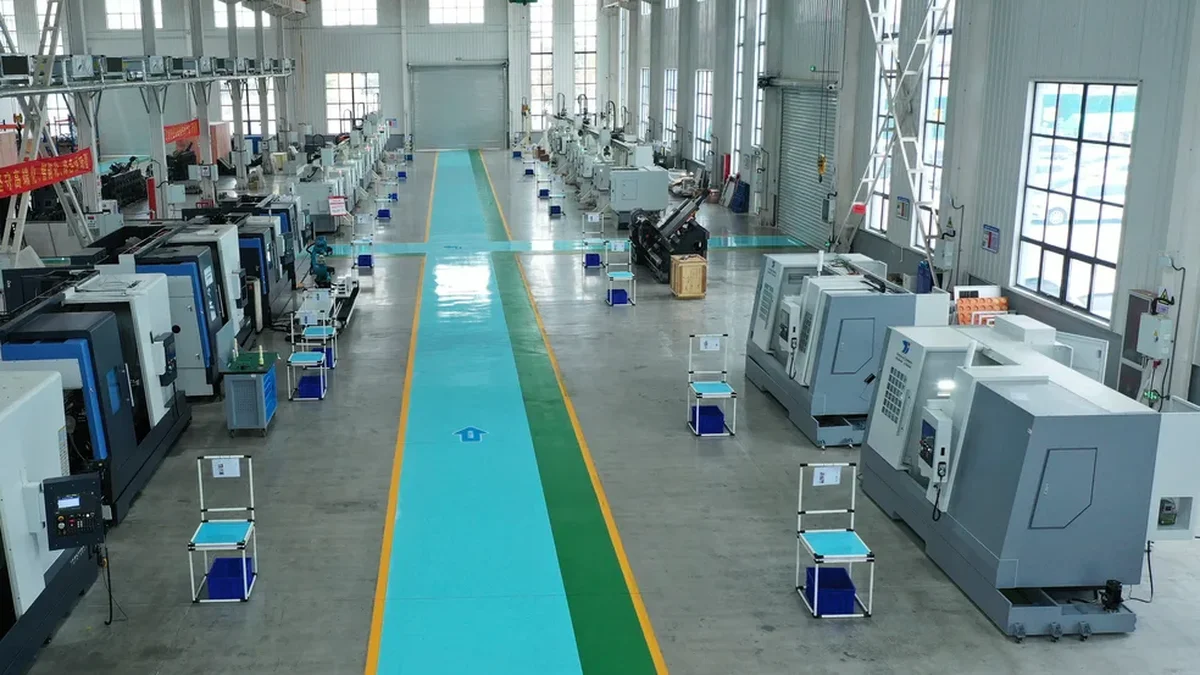
Where the impeller is attached to a shaft or forms part of a rotating assembly, a mill-turn machine avoids a second clamping by turning the hub and milling the blades on the same part without it leaving the spindle. That saves more than cycle time, because it also removes the setup in which the blade tips are most likely to be disturbed.
Balancing, Consistency and the Second Batch
An impeller is a rotating part, so the job is not finished when the last blade is done. Whatever the drawing calls for, the practical point is when the balance check happens: after the last cut, on a finished part, not before the finish when everything is still going to move. Checking early and adjusting the cutting afterwards is how a part ends up certified to one shape and delivered in another.
For a repeat order there are three things worth writing down, and none of them is precision data. The fixture and clamping method that settled the job in. The tools used for each stage, including the reach on the finishing tool. And the sequence, especially where the finishing pass was split. A short log of those three is the difference between the second batch being a batch and being a development project.
Materials change the cutting data but not the logic. Aluminium impellers are unforgiving about chip evacuation and tool pressure; stainless and the higher-strength steels are unforgiving about work hardening and about leaving the tool in the cut too long; cast irons give a stable cut and a lot of dust. The fixture, the datum and the pass structure stay where they were.
FAQ
Can you machine an impeller from a solid blank, or should we cast it first?
Both are routine. A solid blank is usually the right answer for a first article or a small batch, because it needs no pattern and no lead time. Casting or forging becomes worthwhile once the annual quantity is high enough to pay for the tooling, and the machine then finishes what the foundry started. We normally advise running the first article from solid so the process is proven independent of the blank.
Do we need a five-axis machine for an impeller?
Not always. Open, shallow blades can be cut on a three-axis machine with the part on a rotary table. The need for five-axis appears when the blades are deep or twisted, when the space between them closes toward the hub, or when the surface has to be cut from a changing angle to reach it at all. We usually ask to see the part before recommending either way.
How do you stop the blades from chattering?
By shortening the tool for the heavy pass, by supporting the blade roots from below where the fixture allows, and by planning the roughing so that the material supporting the blade is removed last rather than first. On a thin blade the finish pass is light by design; it is there to establish the surface, not to remove the remaining stock.
What materials do you usually machine impellers in?
Aluminium alloys for lower-load and larger parts, stainless and alloy steels for higher-duty impellers, and cast irons for housings and pump sides. We also see bronze and duplex materials on the pump side. The material changes the tools and the cutting data, not the setup logic.
Can you quote from a drawing and a photograph?
Yes. The photograph tells us the blade shape, the space between blades and the finish you are trying to reach. The drawing gives us the datum and the hub features, and the annual quantity lets us price a machine and a fixture rather than just a machine. Send both if you have them.
Send Us the Impeller You Are Planning
If you are preparing an impeller for production, or you have a blade that will not hold its shape between the machine and the gauge, send the drawing and a photograph of the part. We will come back with a machine recommendation and a short note on the setup and sequence, not just a price.
Contact Handemo CNC | Email: sales1@handemocnc.com | WhatsApp: +86 135 6320 3038
Related reading: CNC Machining Thin-Wall Parts | CNC Machining Mold Cavities and Electrodes | CNC Machining Solutions for Automotive Gearbox Housings | CNC Machines for Mold & Die Manufacturing