CNC Machining Brake Discs: Process and Machines
The enquiry rarely arrives from a car plant. It comes from a workshop that rebuilds trucks and buses, or from a distributor who is tired of waiting six weeks for rotors that turn up warped. The question is always the same: can we turn a disc that sits flat on the hub, wears evenly across the friction band, and does not shake the steering wheel at speed. Everything else in the process follows from those three requirements, and none of them is about how fast the machine can cut.
This article looks at how brake discs and disc-type hubs are actually machined: what the part is asked to do, the irons and steels it is made from, the workholding that stops a shallow part from moving when it is cut, and the machines we would put on the job. If your work also covers the axle and hub side of the corner assembly, our note on turning eccentric shafts and the wider automotive parts application guide cover the neighbouring operations.
Why a Disc Is Hard to Machine Well
A brake disc is a short, wide, shallow part, and nearly every difficulty in making one comes from that shape. It is thin relative to its diameter, so it deflects when it is gripped too hard and springs back when the jaws are released. It is cast iron, which is easy to cut but hides sand and hard spots just under the skin. And its two friction faces have to run parallel to each other and square to the mounting face, because a disc that is turned slightly out of square will pull the caliper to one side and wear unevenly.
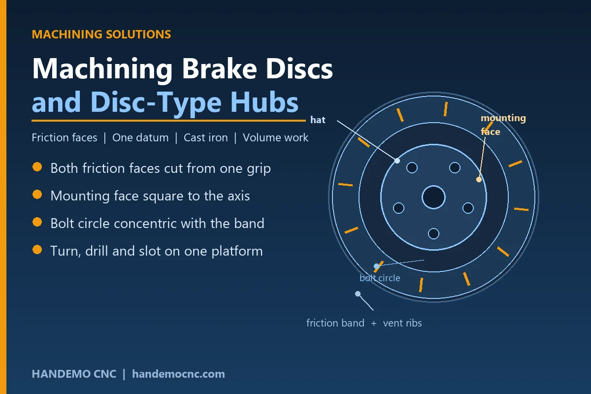
The functional requirements are short. The friction band has to be uniform in thickness around the full circle. The mounting face has to be flat and square to the axis of rotation, because that face is what seats the disc on the hub. The bolt circle has to sit concentric with the friction band. For a vented disc, the internal ribs have to survive the cut without the two faces closing on each other. Nothing on that list is exotic, but all of it depends on the part being held without distortion while it is turned.
Materials You Will See
Most rotors are grey cast iron, and the grade matters more than the name suggests. Ordinary grey iron machines freely and gives a stable friction surface, which is why it has survived a century of alternatives. Higher carbon irons hold up better to heat cycling but produce more dust and a stickier chip, so the tool geometry and the coolant have to change with them.
- Grey cast iron for passenger car rotors and most truck discs
- High-carbon or alloyed cast iron for heavy vehicles and performance applications
- Aluminium hats on two-piece discs, usually bolted or riveted to an iron friction ring
- Stainless and coated irons for corrosion resistance on vehicles that stand for long periods
Casting condition decides your first operation. A rotor that arrives near-net leaves only the faces and the bolt circle to cut, and the cycle is short. A rotor cast thick has to be faced on both sides and will move as the skin comes off, so the machining allowance has to come off evenly rather than in one heavy pass.
The Process Route
Discs are turned in two operations, and the order is chosen so that the faces that matter most are cut last, from a stable grip.
First Operation: Hat and Mounting Face
The disc is gripped on the outside of the hat or on the bore, and the mounting face plus the hat outside diameter are turned in the same clamping. This creates the datum that every later cut is measured from, so it is worth taking a light cut and a finishing pass rather than chasing cycle time on the first op.
Second Operation: Both Friction Faces From One Grip
Here the disc is clamped on the mounting face it has just been given, and the two friction faces are turned in a single setting. This is the step that decides whether the rotor shakes. If the two faces are cut with the part reclamped between them, the thickness will vary around the circle and the customer will feel it through the pedal. Cutting both faces from one grip keeps them parallel by geometry rather than by re-fixturing.
Drilling, Slotting and Balancing
The bolt circle, retaining screws and any cross-drilled holes follow, usually after the faces are finished so that the drilling burr does not end up under a finished face. Slotted rotors are milled with a small cutter following the slot outline. Balancing is the last step: a shallow cut on the outside edge or a few drilled pockets take away the heavy side, and on a vented disc the ribs have to be left alone while that happens.
Workholding Is Where the Project Is Won
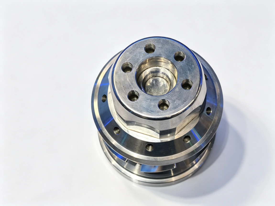
Grip too hard and the disc springs out of round when the jaws open. Grip too lightly and the interrupted cut across the vent ribs will move it. Three habits remove most of the risk.
Machine soft jaws to the diameter of the batch, so the contact is spread around the bore rather than concentrated on three points. Keep the clamping pressure as low as the cut allows, and take the finishing pass with a light depth so the part is not being pushed away from the tool. And for drilled or slotted discs, support the underside of the friction band with a backing plate so the cutter does not press the band down into the gap between jaws.
Two-piece discs add a step. The aluminium hat is usually machined first and the iron ring is finished to match it, so the pair can be bolted and checked as an assembly before balancing. Turn both parts on the same datum and the assembly arrives at the balancing station closer to being right the first time.
Machines We Would Quote for This Work
Disc work is turning work with a small amount of milling attached, so the starting point in our range is a lathe that can hold a wide, shallow part in a chuck without fighting it. The slant bed lathes are built for exactly this, and the TCK70 covers the common passenger car and light commercial sizes. For larger truck and bus discs, where the diameter and the weight of the casting climb, the TCK6350B has the bed and spindle for the job.
Where the disc also needs its bolt circle, screw holes and slots in the same cycle, a lathe with live tooling removes a second clamping and the concentricity risk that goes with it. The power turret machines in the mill-turn range do the turning and the drilling on one platform, and the TCK6050SY goes a step further: the second spindle takes the part after the faces are turned, finishes the hat end, and the operator never has to re-datum the disc by hand.
If your product mix leans toward slotted and cross-drilled rotors in small batches, a vertical machining centre with a rotary table can run the hole patterns as a dedicated cell beside the lathes, and the VMC1160 has the table for a fixture holding four discs at a time. Two-piece assemblies with a complex aluminium hat sit best on a five-axis platform, because the hat's angled and offset features are finished without moving the part; the HTMC800T is the machine we would review for that family.
Running the Cell at Volume
Rotor production is a volume business, and the shop that wins it is the one that keeps the spindle turning. That usually means a bar or billet feeder where the part starts as a casting on a pallet, or a gantry loader where the discs are heavy enough that lifting them by hand slows the cycle. Our automation group builds both, and the practical rule is simple: automate the job that already runs well, not the one that still needs the process fixing.
Tool life on cast iron is stable, which makes it easy to plan a scheduled change instead of cutting to failure. Coolant should be plentiful and aimed at the face rather than the edge, because cast iron swarf is heavy, abrasive and does not clear itself. And because the friction faces are the surface the customer sees and feels, keep a clean wash and inspection station at the end of the cell. A rotor that is geometrically correct but has a burr on the bolt circle will come back.
How We Would Approach Your Parts
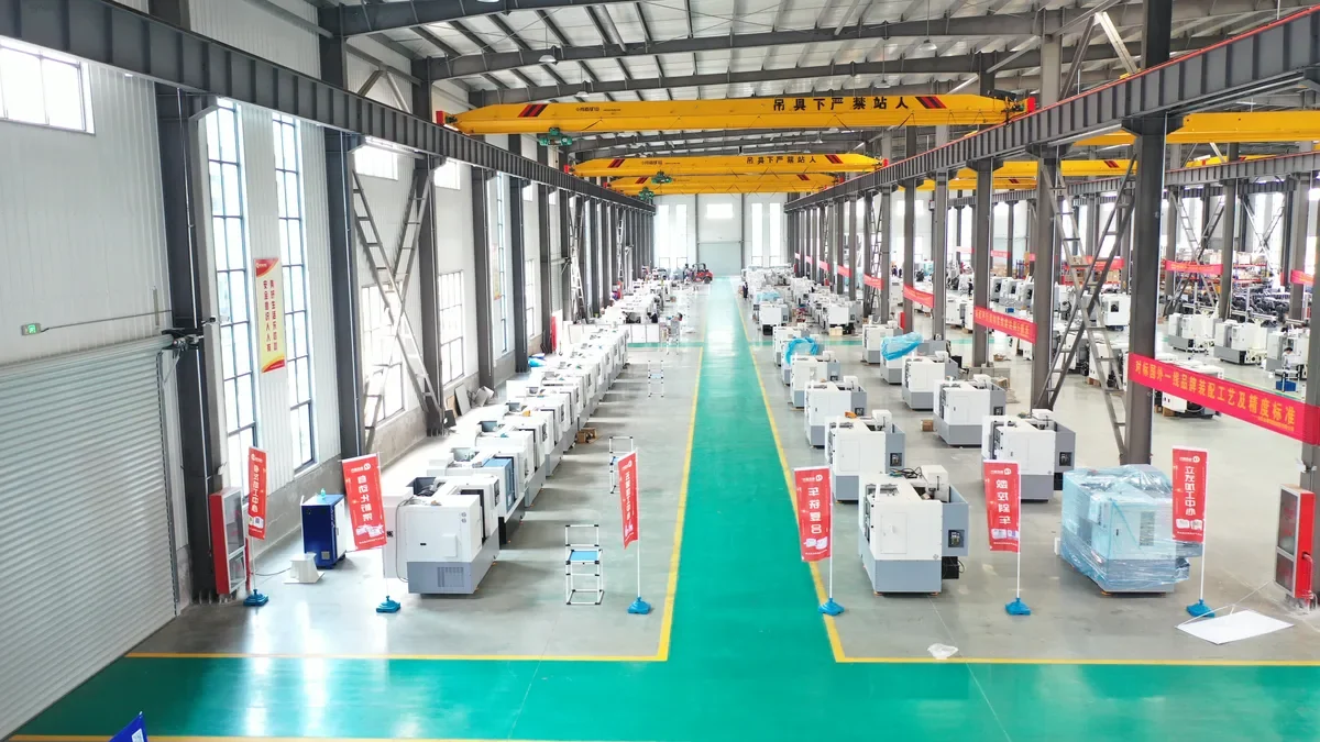
Send us the drawing, the annual quantity and the casting condition, and we will come back with the operation sequence, the workholding, and the machine in our range that carries the cycle. Handemo has been building machine tools since 2008 and supplies buyers in more than 150 countries from a plant of 220,000 m², so we would rather tell you which discs should stay on a two-operation lathe route than sell you a cell that does not suit the volume.
Contact Handemo CNC | Email: sales1@handemocnc.com | WhatsApp: +86 135 6320 3038
Related reading: CNC Machining Thin-Wall Parts | CNC Machining Flange Bearing Housings | CNC Lathe vs Mill-Turn: How to Choose | CNC Machines for Automotive Parts Manufacturing