CNC Machining Wheel Hubs: Process and Machines
A wheel hub does not look like a difficult part. On the drawing there is a flange with a bolt circle, a pilot diameter, and one or two bearing seats inside a fairly short body. Most shops can turn that shape, and most of them can drill the bolt circle afterwards. The trouble starts on the assembly line, when a batch of hubs that all passed inspection will not take a bearing without pressing harder than the last batch did, or when the wheel will not sit flat on the mounting face.
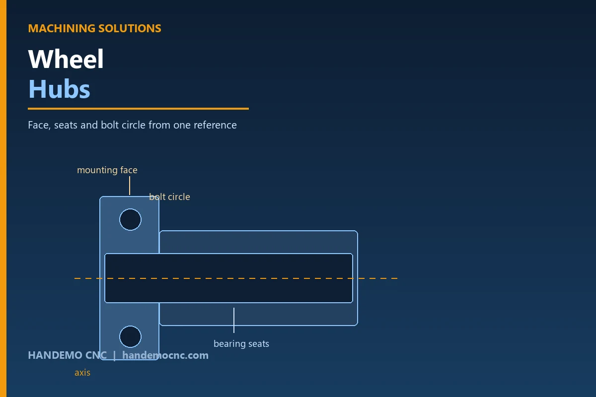
Wheel hubs sit between the wheel and the axle, and they do three jobs at once. They carry the wheel, they hold the bearing that lets the wheel rotate, and they transfer braking and cornering loads into the suspension. Every hub family is a variation on the same set of features: a mounting face the wheel bolts to, a pilot or spigot diameter that centres the wheel, a bolt circle, and one or two bearing bores that have to be aligned with each other. Heavy truck hubs add a brake drum or disc register; trailer hubs add a second bearing seat and a seal bore; small hubs for utility vehicles are often the simplest version of the same design.
What the Part Has To Do
The features on a hub carry different requirements, which is why the process has to be planned rather than improvised. A face that is flat but tilted relative to the bearing axis will clamp the wheel lopsided, and the driver feels that as vibration rather than seeing it as a measurement.
The mounting face closes the joint to the wheel
The mounting face is the surface the wheel sits against. It has to be flat and it has to be square to the bearing axis, because those two conditions together decide whether the wheel runs true. A hub that is finished with the face and the bores coming off different setups can still measure flat and still measure round, and still put the wheel slightly off square. This is the failure that shows up as a wheel that has to be re-torqued twice before it settles.
The bearing seats are the part that really matters
A hub normally carries two bearing seats on the same axis, either two tapered roller cones in a truck hub or a pair of ball or roller seats in a lighter one. Both seats have to be round along their length, and the two of them have to be coaxial with each other. A seat that is slightly out of round will still accept a bearing and still spin; it will also run hot and live a shorter life than the drawing promised. Coaxiality between the two seats is a separate problem from roundness, and it is the one that the customer measures when a hub comes back.
The bolt circle is a position, not a set of holes
Wheel studs or bolt holes are positioned on a pitch circle relative to the bearing axis, and the pattern on your hub has to match the pattern on the wheel, which was made somewhere else. Angular position of the pattern, not just hole diameter, is what decides whether the wheel goes on without opening the holes on site. This is also where shops quietly lose money, because a pattern drilled from a fixture that is bolted and unbolted all day does not come back to the same place every time.
Leave the Face and the Seats on One Axis
Almost every shop that makes hubs already owns the two capabilities the part needs. A lathe makes the bearing seats, the pilot diameter and the mounting face on one axis. A machining center drills the bolt circle and machines any register or pocket in the flange. The real decision is not which machine can do the work — both can reach all of it if you let them — it is which machine holds the reference while the other one cuts.
Finish the seats and the face in the same setup
The single most useful habit is to finish the bearing seats and the mounting face from the same spindle in the same operation. When both come off one turning setup, the squareness between face and axis is produced by the machine geometry rather than re-established by the operator, and nothing can drift between them. For most hubs a CNC slant bed lathe does this comfortably, and long or heavy hubs are run with a steady rest or tailstock so the part is supported while the face and the far seat are cut.
Then put the pattern where the bore says
The bolt pattern is where the process either holds or does not. Drilling the holes in a second operation from a fixture is fine, as long as that fixture reproduces the same angular position on every part. On a fixture that is loaded and unloaded all shift, it will not, and the error is invisible on the part until the customer fits a wheel. The alternative is to make the pattern a programmed position rather than a physical one: locate the part on the finished bore, then let the control place the holes. That is the same argument that decides the route on other automotive parts, and it matters more on hubs because the customer fits a wheel to the result rather than measuring it first.
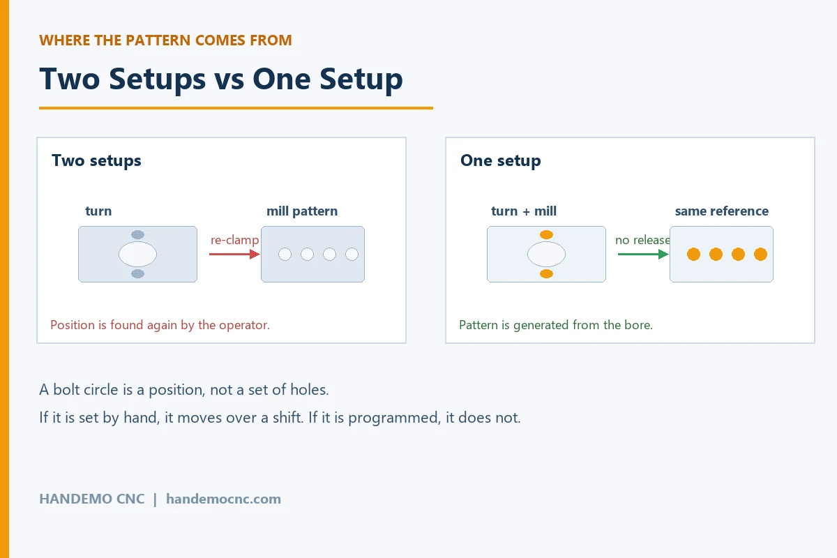
One Setup vs Two: Where Shops Lose the Hub
Two operations are not the enemy. A turning operation followed by a milling operation is a normal, efficient way to make a hub, and plenty of shops run exactly that and get good parts. What breaks is the third operation, the second re-clamp inside the second operation, or the habit of flipping the part to clean up the back face and then coming back to the front.
Every re-clamp redefines where the part is. Most shops handle this by working from a proven datum — the finished bore, a ground spigot, the mounting face — and by leaving enough stock that the finishing cuts remove whatever the clamping did. That works, and it is the right answer for a heavy cast hub. It stops working when the hub is thin, when the flange is large relative to the body, or when the wall between the bore and the outside is thin enough that clamping pressure moves it. In those cases the part springs back after unclamping and the last cut was taken on a shape that no longer exists — the classic cause of a seat that measures round in the machine and pinches the bearing on the bench.
A mill-turn machine or a lathe with Y-axis and live tooling changes that arithmetic. The hub goes on once, the seats, pilot and mounting face are turned on the main spindle, and the bolt circle and any flange pocket are machined without releasing the part. The pattern is then generated from the same bore that will carry the bearing, so the two cannot disagree. For a hub family with a bolt circle plus a machined register, or with features on both faces, that is often the difference between a process that holds and a process that has to be nursed. A mill-turn machine is not needed for every hub, but for a family that keeps drifting it removes the whole question.
Turning Heavy Hubs on a Lathe
On a heavy-duty slant bed lathe, the work is mostly about support and heat. A truck hub is short and wide, which means a shallow overhang with most of the mass outside the chuck jaws, and interrupted cuts around cast bosses are common. A few things matter more than others.
- Support the part properly. A large flange hanging out of the chuck wants a steady rest or tailstock support, especially for the first roughing pass while the casting is still out of balance.
- Rough deep enough to get under the casting skin in one or two passes. Skimming the surface of a cast or flame-cut surface hardens the tool and wastes an insert.
- Bore with the largest bar the seat allows, and keep the bar short. Rigidity here decides finish and insert life far more than spindle speed does.
- Finish the seats and the mounting face in the same sequence, with the part still supported, so nothing has to be re-established afterwards.
- For a thin-wall hub, take the finishing cuts with light clamping pressure. A part clamped hard will finish round and release oval.
The lathe models used for this family split by size rather than by technology. A general-purpose slant bed lathe covers the small and medium passenger-car and utility hubs, while the heavy-duty models take the truck, trailer and agricultural hubs that are too large or too heavy for a standard machine. The practical rule is to size for the largest swing and the longest bore in the family you expect, not for the average part, because the day you need the capacity is the day you get the order.
When the Hub Is Too Square for a Lathe
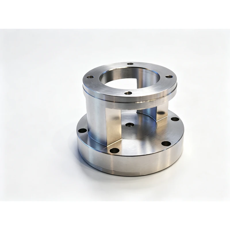
Some hubs cross the line. A hub with machined features on both faces, a combined hub and brake disc adapter, a housing-type casting with a bolt pattern and mounting pads on more than one side — these are milling jobs with a bored feature in them rather than turning jobs with holes in them.
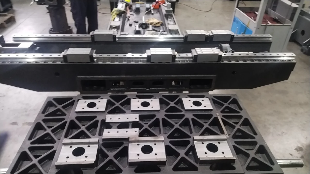
For that group a horizontal machining center makes sense for a reason that has nothing to do with spindle power: the part sits on one face and can be reached on several sides without being turned over by hand, and the opposite face is reached by indexing the table. The bore, the pads and the pattern can then be taken from one station and one coordinate system, which removes the manual re-clamping that causes most of the variation. This is the same reasoning that applies to choosing a machining center for box and housing parts, and hubs with a second machined face land in the same category.
Materials and Cutting Notes
Most hubs are castings or forgings. Ductile iron and cast steel are forgiving to machine: the material breaks a chip, holds a fine finish and does not work-harden, and the only real cost is housekeeping, keeping the dust out of the slides and the coolant tank. Forged steel hubs have no casting skin but bring interrupted cuts and a tougher material; that is usually a tooling decision rather than a machine decision.
Aluminium hubs and hub carriers are common on lighter vehicles and are the opposite problem: soft, sticky, and prone to chips welding to the cutting edge if the tool rubs instead of cutting. They want clearance, speed and volume of coolant, and they want a different approach to clamping, because aluminium moves under pressure even more readily than cast iron. In all of these, the boring operation is the one that decides the result, so the insert and the bar matter more than the model number on the machine.
One note specific to hubs: the mounting face is often the surface the customer's inspection will use, and it is also the surface most likely to be nicked in handling between operations. Covering the finished face, or finishing it last, is cheaper than reworking a part that is otherwise complete. Shops that run this family regularly and hold the whole family on a housing-type parts process usually find the second, third and tenth job go better than the first, because the fixture and the sequence are already settled.
Consistency Across a Batch
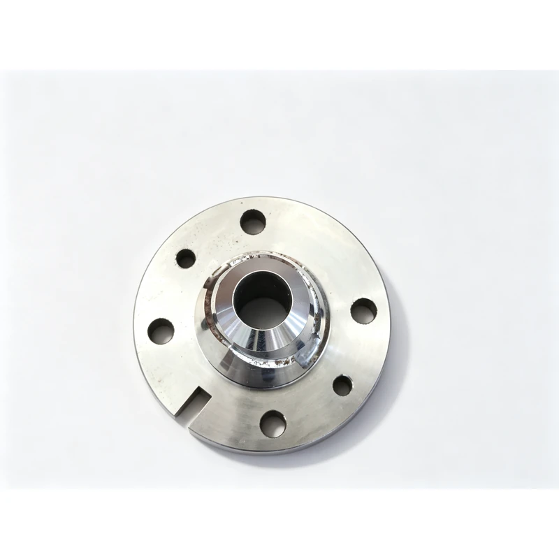
Every hub in a batch is expected to be interchangeable with every other one, and that expectation is set by the vehicle assembly line rather than by the drawing. The habits that protect it are unremarkable, but they have to be followed on every part, not only on the first one.
- Keep the datum the same across the batch. If the first part is set from the finished bore, the last part should be too.
- Check the first part of the shift, not just the first part of the order. A re-clamped fixture drifts over a shift even if nothing has been adjusted.
- Watch the boring bar rather than counting parts. Seat size moves slowly for a while, and then moves quickly.
- Record the setup for the part family. The next order is usually the same hub with a different bolt circle, and the setup is the expensive part of the job.
Frequently Asked Questions
Can a wheel hub be machined on a lathe alone?
Yes, if the bolt circle can be drilled on the same machine or on a drill with a fixture that reproduces position every time. Turning the seats, the pilot diameter and the mounting face on a lathe is the natural route, and it produces the squareness between face and axis for free. The risk is always the second operation for the pattern.
Should I use a mill-turn machine or a machining center for the bolt circle?
A machining center is usually the lower-cost answer when the hub is large, square, or has features on more than one face. A mill-turn machine is the better answer when the hole pattern and the bearing seats must be held to each other and the part is at risk of moving when it is re-clamped.
What causes a wheel hub to run hot or vibrate after assembly?
In most cases it is not the bearing. A mounting face that is not square to the axis will tilt the wheel when the nuts are tightened, and a seat that released oval after unclamping will pinch the outer race. Both come from the process rather than from the part drawing.
How do I choose the size of the lathe for a hub family?
Size for the largest swing, the longest bore and the heaviest part in the family, then check that the machine still has enough spindle speed range for the smaller parts. Buying for the average size leaves you turning work away twice a year.
Is cast iron harder to machine than aluminium for hubs?
No, cast iron is generally easier — it breaks chips cleanly and takes a good finish, which is why so many hubs are cast. Aluminium is softer but stickier, and it deforms more under clamping pressure, so the fixtures and the cutting data take more care.
Working Through a Hub Family?
If you are quoting a wheel hub family and want to know which setup holds across the batch, send the drawing or a photo of the part with the quantity and the material. We will come back with a process route and a machine recommendation sized to the parts you actually run.
Contact Handemo CNC | Email: sales1@handemocnc.com | WhatsApp: +86 135 6320 3038
You can also upload your drawing and get a machining plan and quote back from our process team.