Split Bearing Housing: One Setup, One Bore
A split bearing housing looks like two parts on the drawing and behaves like one in the machine. The base comes in with half a bore in it, the cap comes in with the other half, and neither half is a hole. The hole only exists once the cap is bolted down, and from that moment on it is a long, closed tunnel that you cannot see into, cannot measure from the outside, and cannot fix by taking a light cut off one side.
The housings below came to us as a family of four sizes from a builder of industrial gear units: grey iron bases and caps, matched pairs, delivered with the cap wired to its own base and a stamped number on both. The customer had been boring each half separately and then bolting them together, and the shafts were going in with a preload that nobody could explain until the assembly was stripped and the bore checked from end to end.
This is one of our case studies, written from the shop floor. No test-sheet numbers, no catalogue claims. What the geometry asks for, where the old route leaked money, and what actually changed when the cap started going on before the part reached the machine.
What a Split Housing Actually Is
Take away the drawing and a split bearing housing is three things stacked on top of each other: a joint, a bore, and a mounting face. Each one is easy on its own. The difficulty is that all three have to agree, and the joint sits between the bore and everything else.
- The joint faces. Two flat surfaces that close on each other with a gasket, a sealant bead, or nothing at all. If they are not flat, the cap rocks when the bolts are tightened, and a cap that rocks moves the top half of the bore.
- The bore. A single cylinder that exists only in the assembled state. Its length is the full width of the housing plus the cap, and on the sizes we run that is anywhere from 180 mm to well over a metre.
- The mounting face. The bottom of the base, which has to sit flat on a frame or a foundation and is usually the datum everything else is measured from.
Materials are what you would expect. Grey cast iron such as HT250 / GJL-250 for the general run of gear units and pumps, ductile iron like GJS-400-15 where the housing sees shock or bending, and cast steel for the larger, slower machines where the housing is part of the load path. Small pressed and machined housings in aluminium turn up on lighter duty units, and those bring their own problem: the material moves when you cut it, so the cap has to be on for every cut that matters.
Why Boring the Two Halves Separately Fails
The conventional route is straightforward and it is the route almost everyone starts with. Face the joint on the base, face the joint on the cap, bolt them together, then bore.
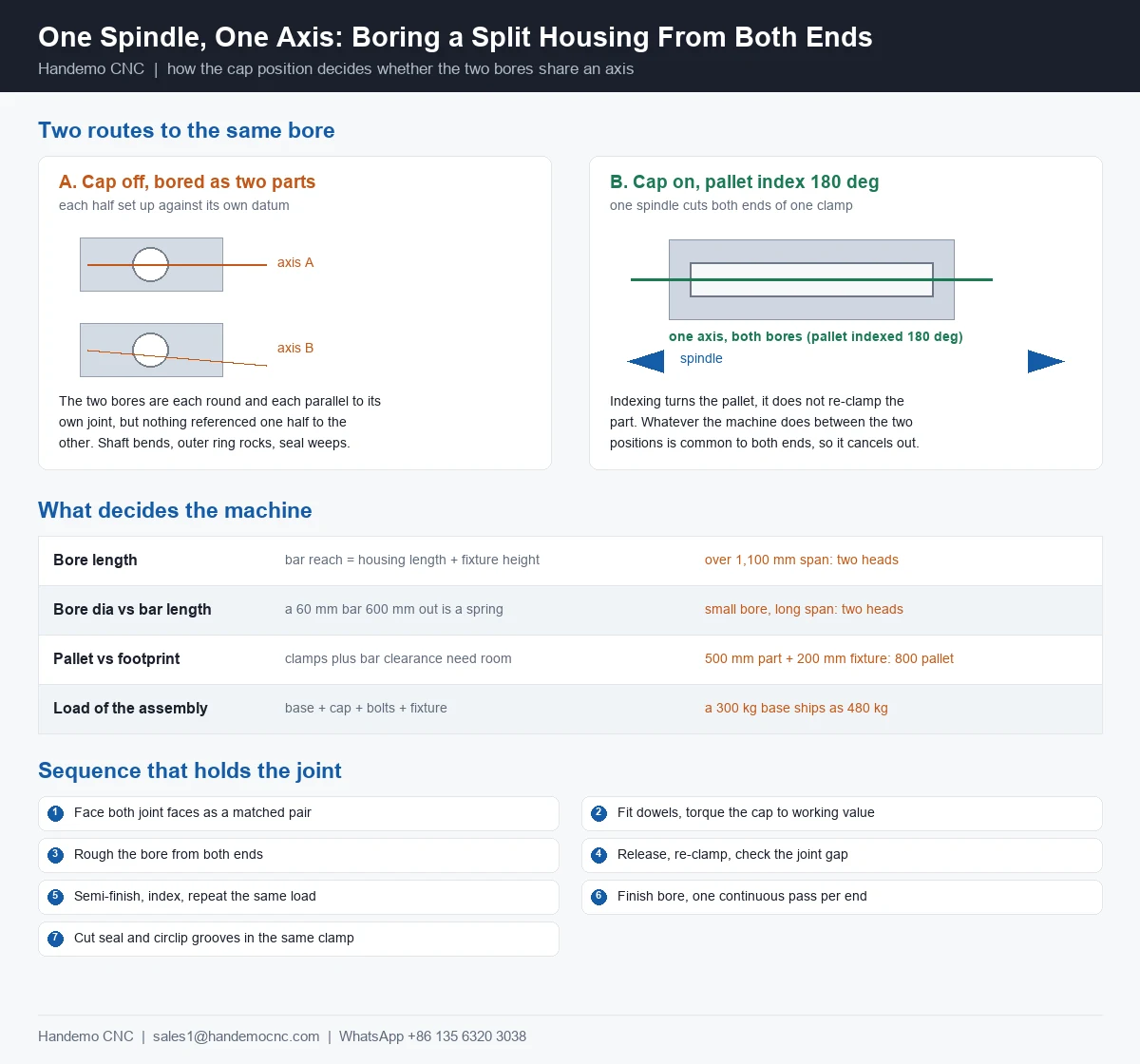
Where it goes wrong is when the two halves are bored as two separate parts and only assembled afterwards. Each bore comes out round and each one is parallel to its own joint face. Bolted together, the pair can still be out of line with each other, because nothing in the process ever referenced one half to the other.
You cannot see this on the bench. The part looks right, the joint closes, the bolts torque down, and the bore measures round at both ends when you check each end on its own. It shows up later, in three ways:
- The shaft goes in tight and comes out hot. Two bores that are parallel but not on one axis force the shaft to bend very slightly across the span. The bearings take that as a side load, and the housing runs warm.
- The outer ring rocks. A bearing seat that is out of line with its partner presents an edge to the rollers. The seat looks fine, the bearing feels fine when fitted, and the outer ring wears a polished band on one side.
- Seals weep. A lip seal follows the shaft. If the shaft is pulled off centre by the two seats, the lip loads on one side and the seal weeps at the bottom of the housing, which is the side nobody looks at.
All three are the same defect wearing different clothes, and none of them can be corrected by re-cutting one half — the error is in the relationship, not in either bore.
What We Changed: The Cap Goes On First
The fix is not a better boring bar. It is a change in the order of operations, and it costs nothing but discipline.
Before the housing is clamped on the pallet, the joint faces are machined flat, the dowels are fitted, and the cap is bolted to its own base with the joint closed. From that point the two halves are one workpiece. It is clamped once, on a pallet, and it never comes apart again until the bore is finished.
Then the boring happens from one side, and the second bore is not a second setup. The pallet indexes 180 degrees and the same spindle, the same boring bar and the same pallet face cut the far end. That is the whole trick, and it is worth stating plainly:
The second bore is not a second setup. It is the same setup, seen from the other side.
Because both bores are generated by one spindle while the part is held in one fixture, the two of them share an axis by construction. The bar does not have to be indicated in twice. The part does not have to be re-clamped against a fresh datum. Whatever the machine does between the two index positions is common to both ends, so it cancels instead of adding up.
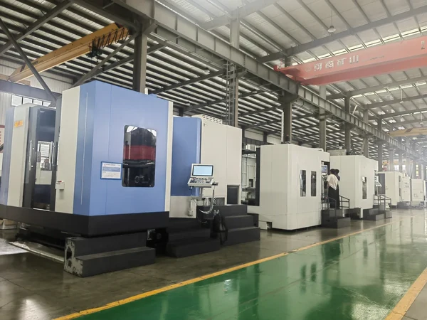
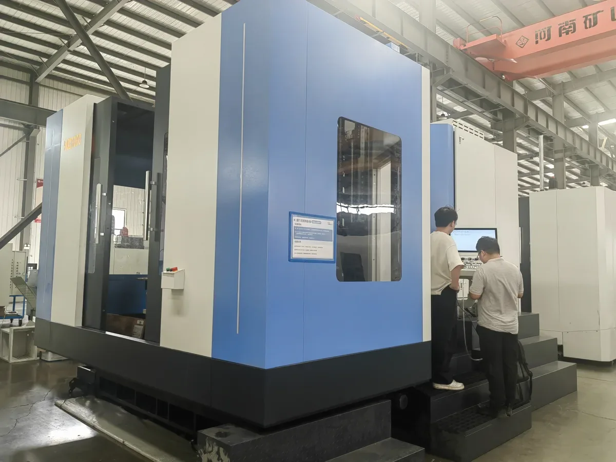
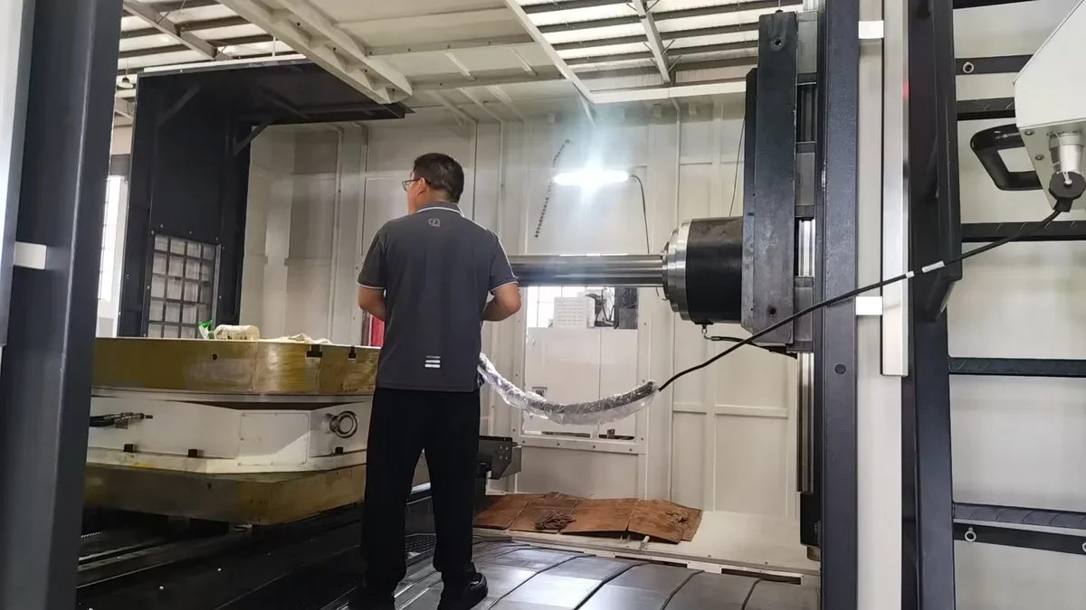
This is the reason a horizontal machining center is the right machine for the job and a vertical is not. On a vertical, the part has to be turned over to reach the second face, and turning a 400 kg housing over is a new setup no matter how careful the operator is. On a horizontal with a pallet, the re-orientation is done by the machine, on a face that was machined as part of the same pallet.
The Numbers That Decide Which Machine
Once the process is settled, machine selection comes down to four measurements and one weight. They are worth doing on paper before quoting, because the cheapest machine that fits the bore is often not the one that fits the fixture.
- Bore length. The bar has to reach the far end with the spindle clear of the near end. Roughly, the reach you need is the housing length plus the fixture height, minus what the spindle nose can advance into the part.
- Bore diameter against bar length. A long bar in a small bore is a spring. A 60 mm bar hanging 600 mm out of a BT50 spindle will deflect under its own cutting load, and the result is a bore that is tight in the middle and open at both ends.
- Pallet size against the footprint. The housing has to sit on the pallet with room for clamps and for the bar to swing clear. A housing that overhangs the pallet is a housing that will move.
- Table load against the assembled weight. The cap, the bolts and the fixture all count. A base that weighs 300 kg becomes a 480 kg assembly before the first cut.
- T-slot pitch against the fixture you already own. If your tombstones and angle plates are built on 100 mm centres, a pallet with 125 mm centres means an adapter plate, and an adapter plate eats Z travel.
| Machine | Pallet | Max load | Travels X / Y / Z | Spindle | Mass |
|---|---|---|---|---|---|
| HMC630-DT | 630 x 630 mm | 1,200 kg | 1,100 / 900 / 1,000 mm | BT50 190, 6,000 rpm | 12,000 kg |
| HMC800-DT | 800 x 800 mm | 2,500 kg | 1,300 / 1,150 / 1,000 mm | BT50 200, 6,000 rpm | 16,000 kg |
| HMC1000 | 1,000 x 1,000 mm | 3,500 kg | 1,300 / 1,100 / 1,200 mm | BT50 190, 6,000 rpm | 18,000 kg |
| TH1000S | 1,000 x 1,000 mm | 4,000 kg | 1,800 / 1,000 / 1,300 mm | BT50 45 degree, 3,000 rpm | 16,000 kg |
| TH1400S | 1,400 x 1,400 mm | 5,000 kg | 1,800 / 1,300 / 1,500 mm | BT50 45 degree, 2,000 rpm | 19,500 kg |
| TH1600S | 1,600 x 1,600 mm | 10,000 kg | 2,000 / 1,500 / 1,800 mm | BT50 45 degree, 1,500 rpm | 24,000 kg |
Two of these numbers are routinely misread.
The first is pallet size. A 630 mm pallet does not take a 630 mm housing. The housing has to be clamped, the bar has to clear the fixture, and on a part that gets bored from both ends the bar has to come out the far side. In practice a 500 mm long housing with a 200 mm tall fixture is already at the edge of a 630 pallet, and the same job on an 800 pallet leaves room to work.
The second is Z travel against bore length. On the TH1400S the Z travel is 1,500 mm, and that is not the bore length you can cut — it is the total movement available, part of which is used reaching past the fixture. If a housing needs a 1,300 mm bore, the machine to look at is not the one whose Z travel is 1,300.
When One Spindle Cannot Reach
There is a limit to the one-spindle approach, and it is the bar, not the machine. Past a certain span the boring bar is long enough that its own weight and cutting load bend it, and no amount of careful feed rate fixes a bar that is springing in the middle of the cut.
That is the case the opposite-spindle boring machine was built for. Two spindle heads face each other on the same bed, and each one bores its own end of the housing at the same time. The part sits still in the middle. On the HM635ST the table is 630 x 630 mm (or 800 x 800 mm on the wider version), rated to 1,200 kg, with X / Y / Z travels of 1,050 / 800 / 850 mm and a BT50 190 spindle in each head. It carries a 24-tool disc magazine and changes tools in about two and a half seconds, and the whole machine stands 6,200 x 3,000 x 2,550 mm at roughly 15 tonnes.
The trade is real and it should be understood before the machine is specified. With two spindles, the two bores are cut by two different heads. Their alignment is a property of the machine — set when it is built and scraped in — not a property of the fixture, and no shim under the part will change it. What you gain is that each bar only has to reach halfway, so each bar stays stiff over its own half of the span, and both ends are cut in the same cycle instead of two.
For the housing family in this case, the 1,100 mm span went on a single-spindle horizontal with the pallet index, because the bar could reach and the volumes did not justify a second machine. For a longer housing, or one where the bore is small against its length, the two-headed layout is the honest answer.
Clamping a Part That Has a Joint in the Middle
Fixturing a split housing is mostly about not undoing what the bolts just did.
- Clamp over the bore, not on it. A clamp directly over the bore squeezes the housing oval, and the bore comes out round only while the clamp is on. Clamp over the thick section of the wall or over the joint flange.
- Support under the joint flange. The joint is the stiffest part of the assembly and the natural place to take the load. Supporting under the base and letting the joint hang puts the whole weight through the cap bolts.
- Never clamp on the split line. A clamp across the joint squeezes the two faces together locally and opens them elsewhere. The bore is then cut into a shape that changes the moment the clamp is released.
- Bring the cap bolts to their working torque before the first cut. The joint closes differently at 40 percent torque than at full torque, and a bore cut with the joint half closed is a bore cut in the wrong shape.
- Keep the dowels in. Bolts locate nothing. If the housing has dowels, they go in before boring and stay in; if it does not, drilling and reaming two dowel holes in the joint is cheaper than a scrapped housing.
The Sequence We Run
- Face both joint faces flat, on the base and on its own cap, and mark them as a pair. This is the only operation where the halves are separate.
- Fit the dowels and bolt the joint closed at working torque.
- Rough the bore from both ends, leaving stock for the finishing passes. This is where the casting skin and any core shift are removed.
- Release and re-clamp, then check the joint for a gap with a feeler gauge. A joint that has opened after roughing will open again later, and the bore would be cut to a joint that no longer closes.
- Semi-finish each end, then index and repeat, so the bar sees the same load in both directions.
- Finish bore in one continuous pass per end, with the bar fed from outside the part so the tool exits rather than stops inside.
- Cut the seal grooves, circlip grooves and oil return slots in the same clamp, from the same bore. A groove cut in a second setup is a groove at an angle to the bore.
- Drill and tap the cap and base bolt holes from the assembled part, so they agree with each other and with the bore.
The order matters more than the individual steps. Every operation that changes the shape of the joint — roughing, stress relief, re-torquing — has to happen before the bore is finished, never after.
What We Need to Quote It
Split housings are one of the part families where a drawing alone is often not enough, because the interesting information is in how the two halves are matched. Send us these and the quote comes back specific rather than general:
- Bore diameter, and the length of the bore in the assembled state.
- The distance between bore centres, if there is more than one bore in the same housing.
- Joint details: bolt size and count, whether there are dowels, and whether a gasket sits in the joint.
- Material, and whether the casting is stress relieved before machining.
- Whether the cap is matched and numbered to its base, or whether caps are interchangeable.
- Seal type and groove dimensions, plus any oil holes that break into the bore.
- Whether this is a new build or a rebuild of a worn housing, because a worn bore has to be measured before it can be quoted.
One thing we do not do is line boring on site. Everything here is machined in the workshop with the housing on a pallet, which is fine for new builds and for rebuilds that can travel, and is the wrong answer for a gearbox that has to stay bolted to its foundation.
If you are not sure whether your housing belongs in the one-spindle group or the two-spindle group, the deciding measurement is the bore length against the bore diameter. Send the drawing through our drawing upload page with that ratio in mind and we will tell you which way we would run it, and why.
Related Reading
Bore work on housings sits between two of our existing guides: the bearing housing machining guide covers the seat itself, and the flange bearing housing process page covers the flange-and-bore family that shares the same fixturing logic. If your part is a closed box rather than a split one, the pump casing case shows how the number of setups is decided by which faces have to agree. For the machine choice behind all of this, VMC vs HMC sets out when a horizontal pays for itself and when it does not.
Frequently Asked Questions
Can a split housing be bored with the cap off?
It can be roughed that way, and often is, because it is easier to clamp two open halves. It cannot be finished that way. The bore only has its final shape when the joint is closed at working torque, so the finishing passes have to be cut with the cap bolted on and the dowels in place.
Does the cap have to be the original one?
On a matched housing, yes. Caps are line bored with their own base, and a cap from another unit will close on the joint but will not put its half of the bore on the same axis. If caps have to be interchangeable, that is a design decision made before the first cut, and it changes how the joint and the dowels are made.
How do you check a bore you cannot see?
From both ends, with a bore gauge or an internal micrometer on a setting ring, at three positions along the length and in two directions. A telescoping gauge and a micrometer work as well and cost less. What matters is that the same person measures both ends the same way, because the useful information is the difference between the ends, not the absolute number.
Why not just bore it on a boring mill?
A boring mill is the traditional answer and it is still the right one for very large single pieces. What it does not give you is the pallet index, so the second end is a second setup, with the part turned or the table rotated and the tool re-indicated. For a family of housings in the 200 to 1,100 mm range, a horizontal machining center with a pallet does the same work with fewer setups per part.
What bore length can you take?
It depends on the bore diameter, because the limit is the bar. As a working rule the span goes up with the bore: a 200 mm bore is comfortable over a much longer span than an 80 mm bore. Send the diameter and the length together and we will tell you whether it runs on one spindle or needs the two-headed machine.
Can you machine the mounting face in the same setup?
Yes, and it is worth doing. The mounting face is usually the datum the bore is measured from, so cutting it in the same clamp as the bore removes one more place where the two can disagree. It does mean the fixture has to hold the part off the pallet, which is a taller fixture and takes Z travel.
Talk to Us About Your Housing
If you have a split housing with a bore that has been giving trouble at assembly, send the drawing and tell us what happens when the shaft goes in. That description usually identifies the problem faster than the drawing does. You can reach us at sales1@handemocnc.com or on WhatsApp at +86 135 6320 3038, or upload the drawing through the quote page and we will come back with the setup we would use and the machine we would put it on.