Cylinder Barrel Machining: A Case Study
The first time I saw this job, there were three barrel-shaped tubes on a bench and one operator with a hammer. He was not hitting the part for fun. He was trying to get a tube off the chuck after boring it, because the jaws had closed on a rough outside diameter, the bore had opened up the wall, and the part had settled into the jaws in a way that made it grip harder the more he pulled. Behind him, a lathe sat with the door open and a boring bar still in the turret.
The shop made hydraulic cylinders for agricultural and construction equipment: barrel, gland, piston rod, end cap. Nothing exotic. The barrels arrived as thick-walled cold-drawn tube, cut to length, and the job was to bore one end, face it, flip it, bore the other end, face it, and put a port in the side. Four operations on a part that weighs between fifteen and forty kilos, depending on the size.
They had been doing it on a general-purpose lathe with a four-jaw chuck. It worked. It also took a full shift to make a dozen barrels, and every barrel was a small argument between the operator, the chuck and the dial indicator. This is what actually changed, and why it changed the way it did.
The part, and what it has to do afterwards
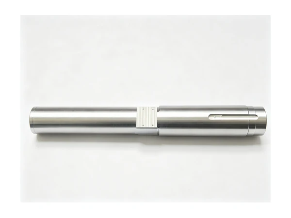
A hydraulic cylinder barrel is a pressure vessel that also happens to be a sliding surface. The bore is where the piston seal runs, so the inside has to be round, straight and free of steps along its whole length. The two end faces have to sit square to the bore, because the gland and the end cap bolt onto them and any tilt shows up as a leak or a scored rod. The port has to break into the bore cleanly, with no burr left inside, because a burr inside a cylinder will cut the seal on the first stroke.
Materials in this shop were mostly ST52 / E355 cold-drawn tube and, for a smaller series, 1045 tube. Both machine well. The difficulty is not the material. The difficulty is that the part is a thin-walled tube once you take the bore out of it, and thin tubes move when you let go of them.
The sizes running through the shop were roughly 180 to 320 mm outside diameter, 140 to 250 mm bore, and 600 to 1200 mm long. That range matters, because it rules out a small lathe and it makes a bar-fed machine pointless: these parts are cut from tube, not from bar.
What was going wrong
The old method was: clamp on the rough OD, bore the first end, face it, unclamp, flip, clamp on the freshly machined OD, bore the second end, face it. Three things went wrong with that, and all three are predictable.
The first is that the second clamping is on a surface that was just machined, so the jaws bite into it and leave marks that have to be dealt with later, or the operator pads the jaws with shim and the part is no longer sitting where he thinks it is.
The second is that the part is no longer a thick tube. After the first bore, the wall is down to somewhere near its finished thickness over half the length. Clamping that on the outside pushes the bore out of round, and the cut you make on the second end is round while the jaws are closed and slightly oval once they open.
The third is the one that cost the most time: the operator had to indicate the part in again for the second end. On a tube of this size, that is ten to twenty minutes of tapping with a soft hammer and watching a dial, and it produces a different result every time because it depends on how the operator felt that morning.
What changed: sequence first, machine second
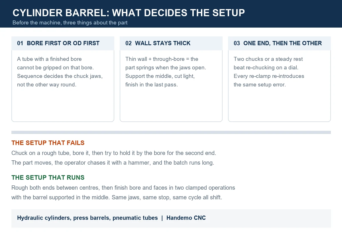
The fix was not a bigger chuck. It was deciding the sequence before choosing the machine, and the sequence that worked was this:
- Cut the tube to length with a small allowance on both ends, and chamfer both ends on a band saw or a dedicated chamfering station so the part can sit in a steady rest without a burr pushing it off centre.
- Rough bore both ends, leaving stock in the bore and on both faces, holding the tube on the rough OD with soft jaws, with the part supported in the middle by a steady rest.
- Finish the bore from one end through as far as the bar reaches, then finish the second end from the other side, and face both ends square to the bore in the same clamping as the finish bore.
- Put the port in as a separate operation, either on the same lathe with a driven tool or on a small machining centre with a fixture that locates on the finished bore.
Two things in that list are doing the real work. One is that the finish bore and the face happen in the same clamping, so the face is square to the bore by construction instead of by re-chucking. The other is that the steady rest carries the middle of the tube, so the jaws only have to stop the part rotating and sliding, not hold it straight.
That change alone cut the second-end setup from a dial-indicating exercise to a stop-and-clamp operation. On this job it took the barrel from roughly one per forty minutes to one per twelve, with one operator running two machines.
The machine side
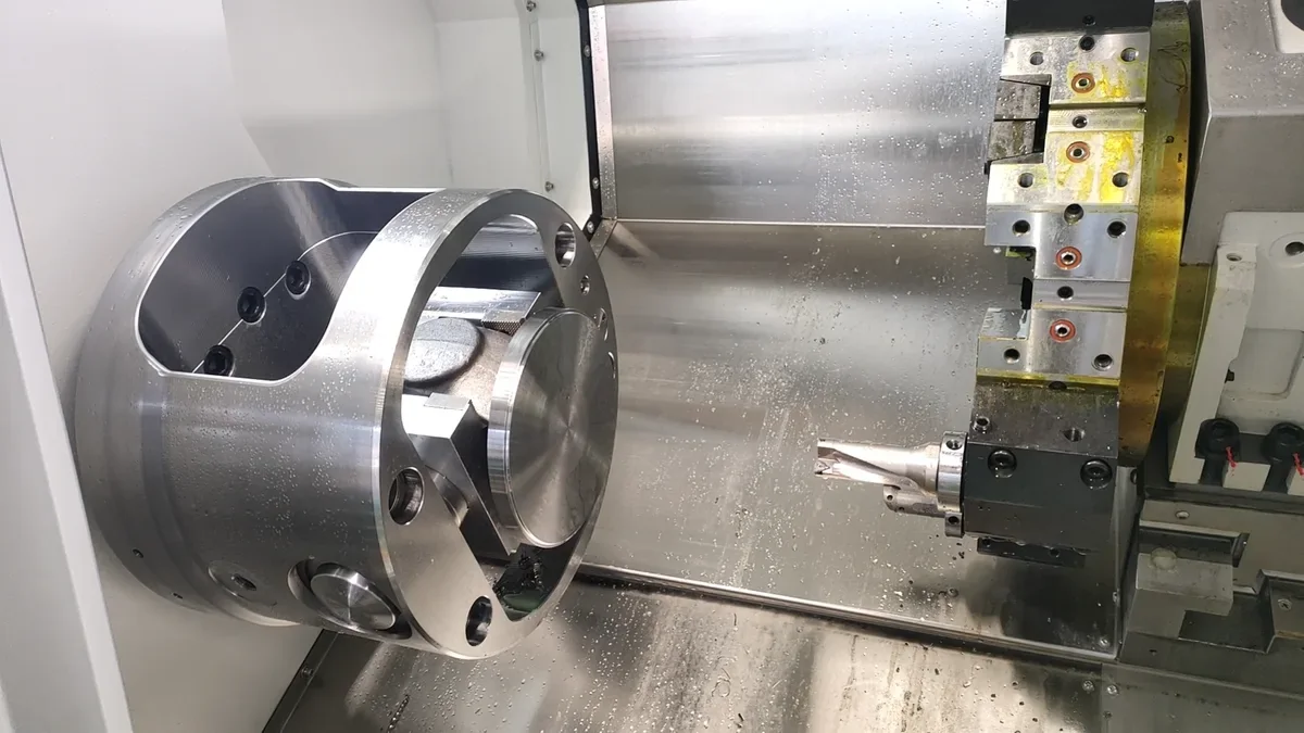
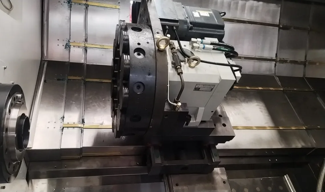
The shop moved the job to a heavy slant bed lathe with a large spindle bore, and the reason is spelled out in the numbers rather than in adjectives. On the TCK80B-1500, the spindle nose is A2-11, the spindle bore is 120 mm, the machine takes a 12-inch chuck, the spindle motor is 22 kW, maximum cutting length is 1500 mm, maximum cutting diameter is 800 mm, and the machine weighs 12,000 kg. The bed is a hard rail structure, which is what you want when a boring bar is hanging a long way out of the turret.
A shorter version of the same job fits the TCK6350B: 630 mm turning diameter on the bed, 96 mm spindle bore, A2-8, 18.5 kW, 500 mm cutting length on the standard model and 1000 mm on the -1000 version, with a 12-station servo turret and roughly 4,300 kg of cast iron underneath it. For a barrel up to about 500 mm long, that machine does the whole job without the part hanging out of the back of the spindle.
The spindle bore matters more than people expect on this part. A 120 mm bore means a barrel up to 105 mm over the bar can pass through, which is not the case here, but it also means the boring bar and the coolant line can be fed from the rear of the spindle and the chips fall away from the cut instead of piling up in the bore. On the smaller TCK50, the bore is 65 mm and the bar capacity is 50 mm, which is fine for gland nuts and small piston parts but not for these barrels.
Jaws, stops and the small things that decide the batch
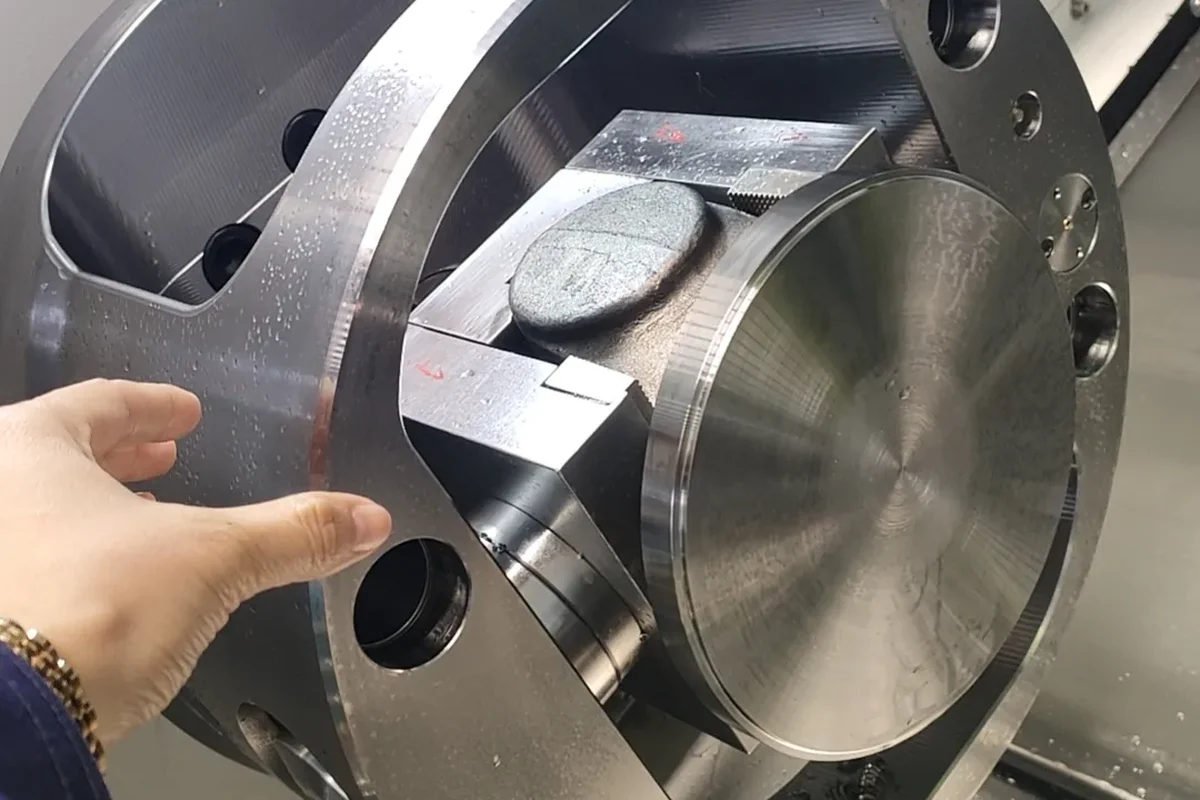
Soft jaws bored in place on the machine, at the diameter of the part, with a stop in the spindle. That is the whole fixture. It sounds too simple to be the fix, but three details made it work:
The jaws were bored with the part clamped at the same pressure used in production, so the jaw shape matches the part as it is actually held. Jaws bored at a different pressure are a different shape.
The stop was set on the finished end face, not on the rough end, so the length of the part is set by a machined surface and the same stop could be used for the second end after the flip.
And the jaws were marked for the two ends. The operator clamps the part in the same orientation every time, so if there is any residual run-out in the chuck, it repeats the same way instead of averaging out to a different error on every part.
None of these are machine features. They are decisions about how the part is held, and they are the reason the same lathe can produce a batch that all fits and a batch that has to be sorted.
Chips, coolant and the inside of a tube
Boring a tube is a chip evacuation problem before it is a cutting problem. The bar is inside a closed cylinder, the chips have one way out, and if they are not pushed out they get re-cut, which is how a boring bar wears out in the middle of a batch and how a bore gets a scored band that nobody can explain afterwards.
What worked here was through-tool coolant at pressure, a boring bar with a positive rake insert and a chip breaker matched to the feed, and a program that pauses the feed long enough at the end of each pass for the coolant to clear the bore before the bar retracts. The pause costs a couple of seconds per pass and saves a scrapped barrel.
The other thing that helped was cutting the bore in two directions rather than one. Rough from the front, then finish from the front for the first half, then index the part and finish the second half from the other end. The bar overhang stays short, the bar does not sing, and the bore is straighter than a single long pass.
The port, which is where batches actually die
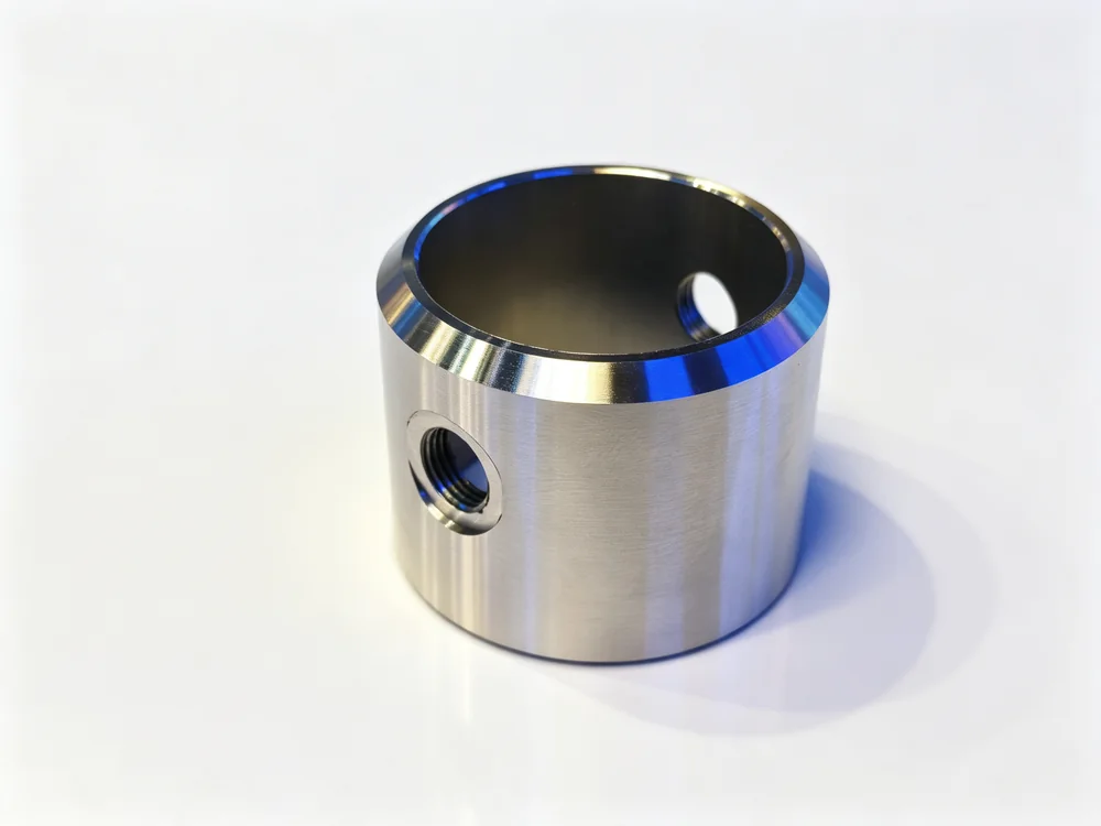
The side port is a small feature with a large ability to ruin a finished part. Drilling and tapping into a finished bore leaves a burr on the inside wall, and that burr is directly in the path of the piston seal. If the port is drilled after the bore is finished, someone has to deburr inside a tube that is 250 mm in diameter and 900 mm long, which is exactly as pleasant as it sounds.
Three ways to handle it, in order of how well they work:
Put the port in before the finish bore, so the finish boring pass removes the burr as it goes. This requires the port position to be known relative to the bore, which means it has to be done in the same clamping or with a fixture that locates on the bore.
Or do the port on a machining centre with the barrel standing on its end face in a fixture that locates on the finished bore, and deburr with a back-chamfering tool through the port. This is what most shops end up doing once the volume is high enough to justify the fixture.
Or use a driven tool on the lathe, if the machine has one, and bore the port from inside out with a small boring bar. It is slower per hole and it leaves a clean edge. On the TCK56Y type of machine, with a power turret and a Y axis, the port and the face holes can be done without a second setup, which is the reason shops doing hydraulic work move to mill-turn in the first place.
What the batch looked like after the change
The shop ran three sizes on the same machine: a 180 mm barrel at 600 mm long, a 250 mm barrel at 900 mm long, and a 320 mm barrel at 1200 mm long. Changeover between sizes was soft jaw change plus stop adjustment plus program call, roughly forty minutes, and the first part off each changeover was checked and then the batch ran.
The measurable change was not a number on a specification sheet. It was that the second-end setup stopped being a skill, the scrapped barrels stopped coming from the bore and started coming from the port (and then stopped altogether when the port moved before the finish bore), and one operator could run two machines instead of standing at one with a hammer.
That last point is usually the one that pays for the machine. If a shop needs one operator per lathe because every part needs indicating in, the machine is only as fast as the operator's patience. Take the indicating out of the job and the same person can load, unload and check two machines.
When this approach does not fit
If the barrel is a honed tube bought finished inside, do not bore it. Cut, face, chamfer, and put the port in with a fixture that does not touch the honed surface. Boring a honed tube removes the honing and you cannot put it back with a boring bar.
If the wall is very thin relative to the diameter, the steady rest has to be padded and the cut has to be light, and sometimes the answer is to bore the part in a fixture that supports it along its length rather than in a chuck at all. A three-jaw chuck on a thin tube is a device for making an oval.
If the part is short and the volume is high, a bar-fed lathe or a twin-spindle machine is the better answer, because the handling time dominates and passing the part from spindle one to spindle two removes the flip entirely. That is a different article and a different purchase.
And if the shop makes five barrels a month, none of this matters. A used lathe, a four-jaw chuck and an operator who is good with a dial will be cheaper than any of the above, and the money is better spent on a second-hand boring head.
Questions that come up on this job
Does the barrel have to be bored from both ends?
Only if the bore is longer than the bar can reach without chatter. On a 600 mm barrel with a 120 mm bore, one pass from one end is possible with a heavy bar and a steady rest. On a 1200 mm barrel it is not, and the part gets indexed. The decision is made by the bar, not by the drawing.
Can the port be drilled on the lathe instead of a machining centre?
Yes, if the lathe has a driven tool and enough Y axis to reach the wall. It is slower per hole than a machining centre with a fixture, but it removes a whole setup and a whole transport step, which on small batches is the better trade.
Why not just buy a bigger chuck and hold the part harder?
Because the problem is not grip. A thin tube held harder is an oval tube. The jaws need to locate the part, the steady rest needs to support it, and the cut needs to be sequenced so that the finished surface is not used as a clamping surface.
What about welding the end caps before machining?
Some shops weld the cap on and then machine the assembly. It works, and it puts the weld distortion into the machining allowance instead of into the finished bore. The catch is that the part is now longer and heavier, and it cannot be passed through the spindle, so the machine needs enough swing and a steady rest that can take the weld seam.
How do you check the bore without a bore gauge?
On this size of part, most shops use an internal micrometer or a bore gauge at three positions along the length and two directions, and check the roundness at the ends where the seals sit. The check is not the hard part. Making the part so that the check passes on the first attempt is the hard part, and that comes from the sequence, not from the instrument.
Next step
If you are setting up a barrel or tube job and want to know which machine in the range will take the part through the spindle, hold it in a steady rest and reach the bore in one or two passes, send the drawing and the batch size. We will tell you which model fits and what the fixture has to look like, including whether the port belongs on the lathe or on a machining centre.
Contact Handemo CNC | Email: sales1@handemocnc.com | WhatsApp: +86 135 6320 3038
More jobs like this one are in our case studies, and the wider process notes for this part family are in the hydraulic cylinder application guide.