Case Study: A Thin-Wall Motor Plate in One Setup
The first shipment of these motor plates came back with a note that read, roughly: the bore is not round. Not by much, and not enough to see by eye, but enough that the bearing would not seat by hand the way it did on the sample. The customer had measured the part on a CMM, found the bore oval, and sent three photos of the report. What made it awkward was that the shop had measured the same bore before shipping, and their reading had been fine.
Both measurements were honest. The part was changing shape between the two readings, and the reason sat in how it was made: it had been turned in three separate chuckings, and each chucking was holding a different surface.
What the part actually is
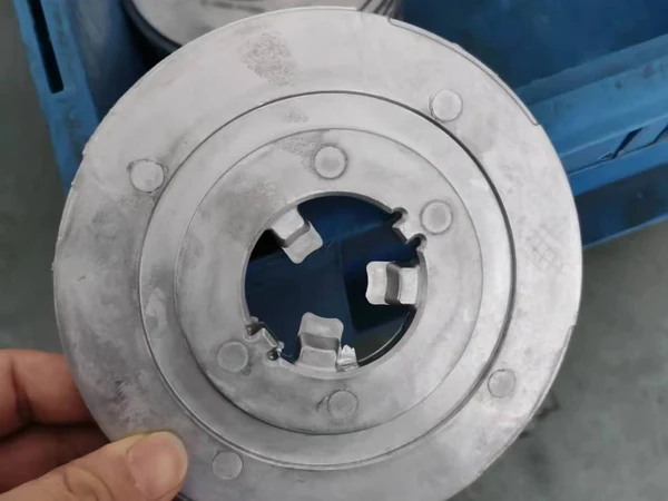
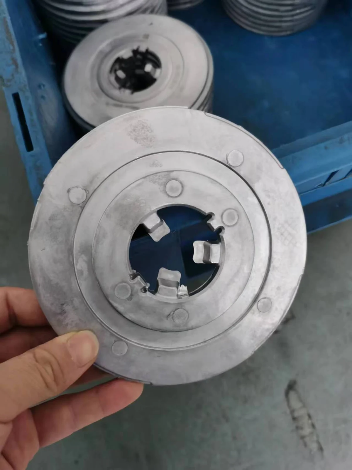
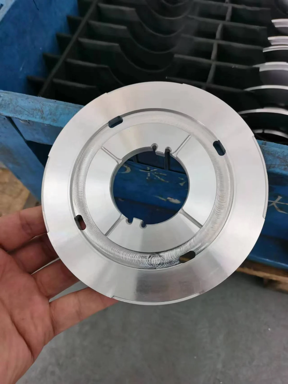
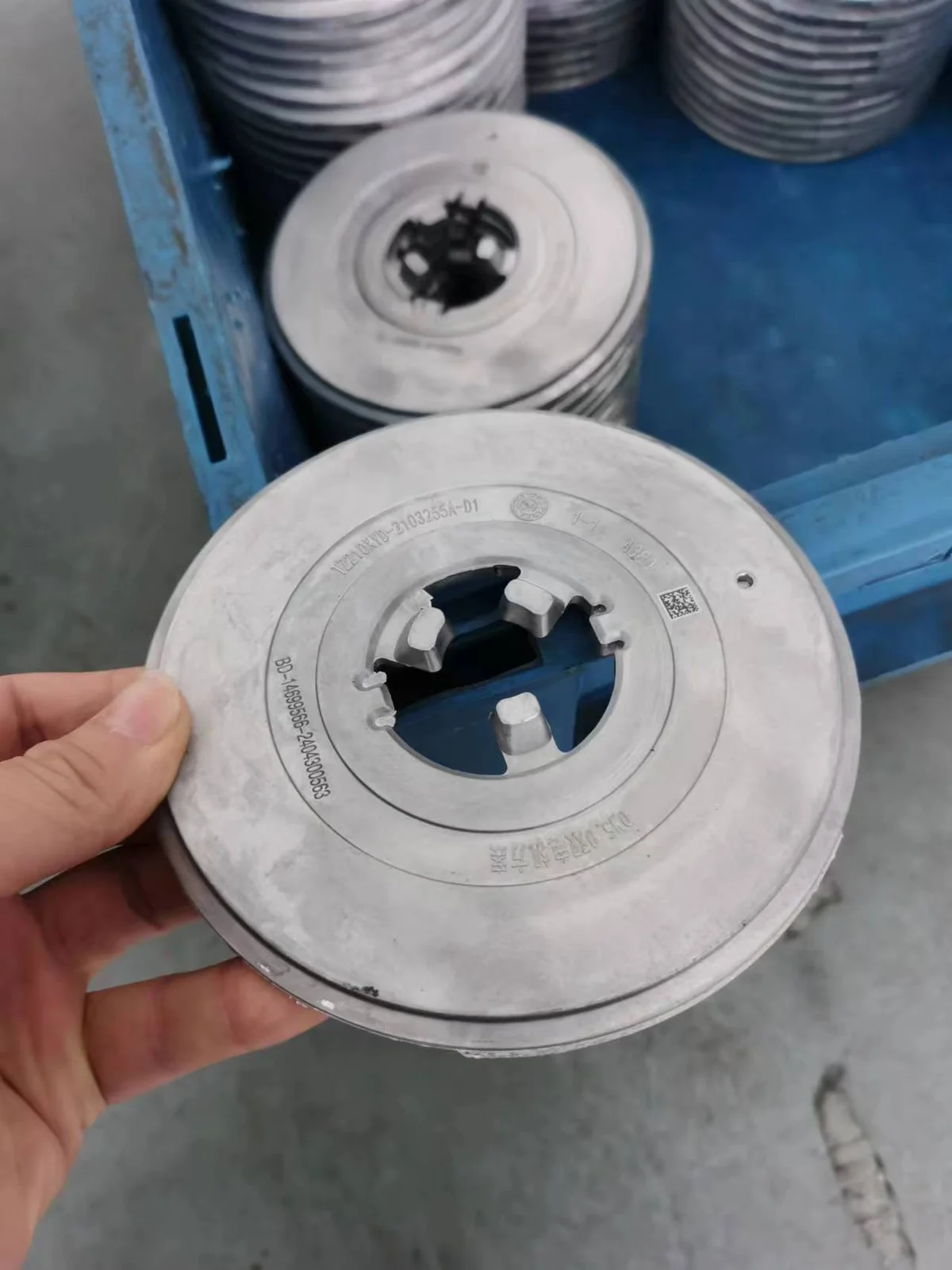
It is a flat aluminium plate, roughly 260 mm across the outside, with a large central bore, four milled windows around that bore, and a ring of bolt holes. The wall between the bore and the outside is about 4 mm. It sits inside an electric traction motor, where it separates the rotor cavity from the winding end and carries a bearing on the centre bore.
The material in this case was a 6061-type aluminium, cast near net shape and then machined on the faces, the bore and the windows. That combination is common for this family of parts: casting keeps the cost down, machining has to bring the bore, the faces and the window edges into one relationship. Nothing about the part is heavy. Nearly everything about the part is flexible.
Why three setups kept producing a bad bore
The original route was the obvious one. Turn face A and rough the bore. Flip, turn face B and finish the bore. Then move to a machining centre, clamp on the finished bore, and mill the four windows.
Each of those steps is reasonable on its own. Together they created three problems that only appear once the part is thin.
The two faces were turned from two different grips
Turning face A in one chucking and face B in another means the two faces are parallel to each other only as accurately as the second clamping repeats. On a heavy part, the error is buried in the stock. On a 4 mm wall, the part simply bends to fit whatever the jaws impose, and then springs back when the jaws open. The faces end up non-parallel in a way that no single measurement catches, because each face is flat on its own.
The bore was clamped on a cast surface
When the part is held on the rough outside diameter, the three points of the chuck press the casting into a slightly triangular shape. The boring bar then cuts a round hole in a part that is temporarily out of round. Release the chuck and the part returns to its own shape, taking the bore with it. This is the classic thin-ring trap, and it is why the shop's own measurement looked acceptable: they measured while the part was still supported, or immediately after, before it had fully relaxed.
The windows were cut after the bore was finished
Milling four windows removes a large amount of material from one side of a ring that has already been finished. The stiffness of the ring drops, the residual stress from the casting and from the earlier cuts redistributes, and the bore moves. On this part the movement was described by the customer as the bearing no longer seating by hand. The order of operations, not the cutting parameters, decided the outcome.
The route that worked: one chucking, driven tools
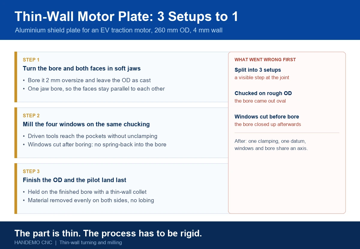
The fix was to stop thinking of the part as a turning job followed by a milling job, and to treat the bore and the windows as features of one setup. That means a lathe with driven tools on the turret, so the part never leaves the chuck between the bore and the windows.
Step 1: soft jaws, bore and both faces
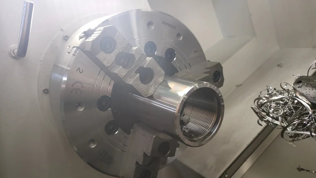
The part is gripped on the cast outside diameter in bored soft jaws, and the jaws are bored in place so that they wrap the casting rather than press on three points. The bore is then cut slightly oversize and deliberately left that way, both faces are turned in the same chucking so they are parallel by construction, and the pilot land for the bearing is left with finishing stock.
Boring oversize on purpose feels wrong the first time. It is the only way to keep the finishing cut for a stage where the part is held on a surface that already exists and is already round.
Step 2: the windows, still in the chuck
With the part still clamped, driven tools in the turret come in from the face and mill the four windows. A Y-axis turret is what makes this practical: the tool can work off the centreline, so a window that is not centred on the bore is still reachable without unclamping. Window edges and the bore now share one axis because they were cut without the part ever moving.
This is also the stage where the part is at its weakest, and it is the reason not to finish the bore first. Cutting the windows here lets the ring relax while there is still material left in the bore to remove.
Step 3: finish the bore and the outside last
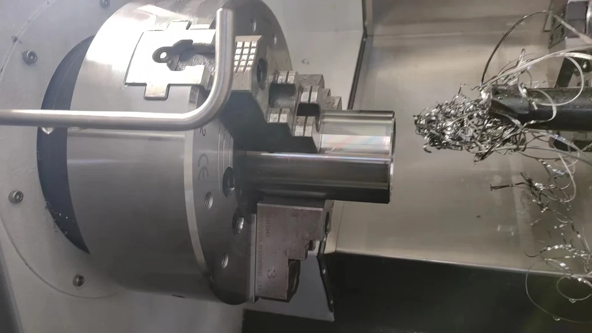
The part is then held on the finished bore with a thin-wall collet or a purpose-made expanding mandrel, and the bore, the pilot land and the outside diameter are finished. Because the grip is now a round surface that was itself cut in this process, the clamping force is evenly distributed around the part instead of concentrated at three points.
The outside diameter is cut after the windows, not before. If it were cut first, the windows would relieve the ring and leave the outside slightly out of round, and the outside is what the part is often located by at assembly.
What the machine has to be able to do
This route needs three things from the machine, and it is worth checking all three before quoting a part like this.
Driven tools with a Y-axis. Without Y, windows that sit off the bore centreline force either a second setup or an interpolated cut that is hard to keep clean at the corners. A power turret with a Y-axis stroke in the range of plus or minus 50 mm covers most plates of this size.
Enough bar and bore capacity for the mandrel. The finishing stage holds the part on an expanding mandrel that has to pass through the spindle bore or be supported between centres. A 65 mm spindle bore and a 50 mm bar capacity, as on the TCK6050, is comfortable for this family of parts; larger plates with bigger bores move up to the TCK6350B.
A chuck that can be soft-jawed and re-bored quickly. The whole method depends on jaws that match the casting. If changing jaws takes an hour, the shop will go back to three setups on the next batch.
For the combined turning and milling work in one clamping, the TCK6050Y is the machine this case was run on. It carries the same 560 mm swing over bed and 65 mm spindle bore as the plain lathe, adds the Y-axis power turret, and comes in a 500 mm and a 980 mm turning length so the same process carries over to longer motor housings. Where the volume justifies two ends at once, the TCK6050SY cuts the second operation entirely.
For the milling side of a plate that is too large for a lathe chuck, the same window and hole pattern is normally cut on a vertical machining centre with a fourth axis, and the bore is finished on a lathe before the plate is clamped on a fixture that supports the full ring. The VMC1160 is the usual size for plates up to about a metre; beyond that the VMC1370 gives the extra table and travel with the same 800 kg table load.
Holding the shape, not just the size
The measurements that matter on this part are not the ones a drawing usually calls out. A plate like this can pass every dimensional check on the bench and still fail at assembly, because the bore is round in the fixture and not round in the motor. Three habits kept it right in production:
The part is measured free, on three points, after it has been allowed to settle. Measuring in the chuck, or immediately after release, hides exactly the movement the process is trying to avoid.
The bolt hole pattern is drilled in the same clamping as the windows. Holes that locate the part at assembly are the ones that must share a datum with the bore, and drilling them later re-introduces the setup problem the whole route was built to remove.
The first part of every batch is checked on a surface plate for flatness across both faces before anything else. If the faces are not parallel, nothing downstream will be stable, and it is cheaper to find that at part one than at part two hundred.
Marking and traceability
Motor plates in automotive supply chains usually carry a part number and a traceability code. On this part they were laser marked on the outer ring, away from the bore and away from any sealing face, in the same clamping as the finishing cut. Marking after the part has been released from the chuck is fine for identification but adds a handling step and a chance of a burr on a face that has already been finished.
The general lesson
Thin-wall parts do not fail because the machine is not stiff enough. They fail because the process asks a flexible part to hold a shape it cannot hold. Every extra clamping is a new chance for the part to be forced into a shape that is not its own, and every operation that removes a lot of material after a finished feature will move that feature.
The practical rule that came out of this job: finish the features in the order that leaves the part strongest for the longest, and cut the windows while there is still stock in the bore to absorb the movement. It sounds like a small change to the route. It removed an entire operation and the complaint that came with it. More on the general case is in CNC machining thin-wall parts, and the housing side of the same motor family is covered in EV motor housings.
Questions we get on this type of part
Can the windows be milled on a lathe without a Y-axis?
For windows centred on the bore, yes, using the C-axis and interpolating. For windows offset from the centreline, a Y-axis turret removes the compromise between a second setup and a weaker corner. If the design has offset windows, specify Y from the start rather than discovering it at the fixture stage.
Is a cast blank always better than a billet for this part?
At this size and wall thickness, a casting is usually cheaper and closer to shape, but it carries its own stress pattern that shows up when material is removed. A billet gives more predictable behaviour and a higher material cost. For prototypes, billet is often the faster route because there is no pattern to make.
How do you hold the part for the finishing cut without marking it?
Soft jaws bored to the actual casting, or a thin-wall collet on the finished bore, with clamping pressure set low enough that the part is driven rather than crushed. On aluminium, a light spring pass at the end of the finishing cut also removes the marks left by the jaws seating.
What if the plate is too big for the lathe swing?
Then the bore and the faces go on a vertical machining centre with a boring head or a large-diameter face mill, and the plate is clamped on a full-ring fixture rather than on three points. The process order stays the same; only the machine changes.
How many parts before the process is stable?
Usually the first part tells you whether the order of operations is right, and the third or fourth tells you whether the clamping is repeatable. If the bore moves between part one and part ten, the problem is the grip, not the cutting data.
Contact Handemo CNC | Email: sales1@handemocnc.com | WhatsApp: +86 135 6320 3038