Case Study: Machining a Long Reducer Shaft
The shaft came in wrapped in a length of cardboard and a strap, about as long as a dining table, and it had a bend in it that you could see if you sighted along it against a window. It had already been turned once, somewhere else. The journals were round. The problem was that the two ends did not agree with each other, and the customer was bolting it into a reducer where it would spin all day at a few hundred revolutions a minute and drive a gear on one end.
This is a common way for a shaft job to arrive. Nobody argues about whether a shaft is round. What decides whether the assembly is quiet or noisy is whether the whole part is straight, and whether every feature on it was cut from the same axis. A shaft is one of the simplest shapes in a machine shop and one of the least forgiving, because there is nowhere for an error to hide along a metre of steel.
What follows is how a shaft of that family was reworked and then produced as a batch here: what the part does in the machine it goes into, why the first shop's route struggled, and what actually settled the job. It is part of our case studies series, where each article follows one real part through the floor and explains the decisions rather than only the result.
What the part actually is
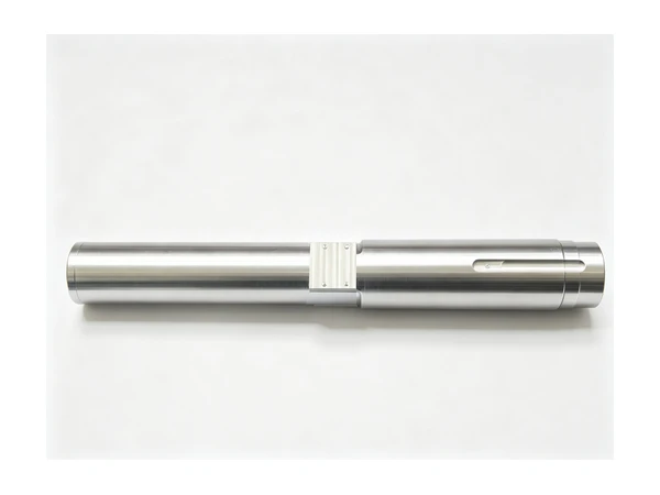
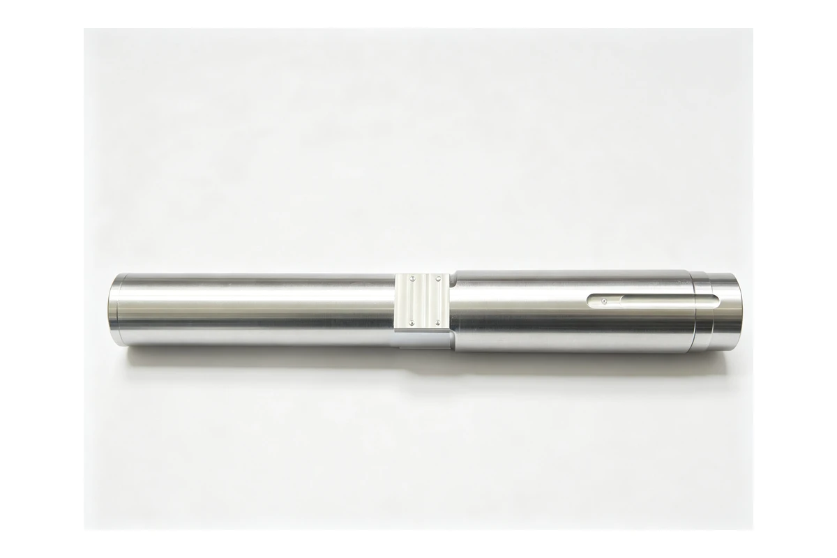
The customer builds speed reducers for conveyors and mixers, and the shaft in question is an input shaft: the part that carries a pulley, coupling or motor on one end and a gear on the other. It is a stepped round part, roughly 700 mm long, with four working diameters between about 60 and 90 mm, a shoulder at each end of the gear seat, a keyway where the gear sits, a keyway or a coupling fit at the drive end, a threaded end for a retaining nut, and a centre hole at each end.
Every one of those features has a job, and they are not equal:
- The two bearing journals carry the shaft in the housing and set where the axis is.
- The gear seat has to be concentric with those journals, or the gear runs off centre and the mesh is uneven around the tooth.
- The shoulders have to be square to the axis, because they act as the stops that position the bearings and the gear.
- The keyway and the drive end locate by angle as well as by diameter, so their position relative to the gear seat matters, not just their size.
- The centre holes are what every later operation refers back to.
Put in one sentence: the journals define the axis, and everything else has to be true to it. That is the whole job, and it is why a shaft that looks acceptable on a bench with a micrometer can still be scrap once it is assembled.
Reducer work sits next to a family of parts we cover separately, the gears themselves, and before the shaft there is often a bushing or sleeve in the same assembly. A shaft is the part that ties them together, so it is the one that gets blamed when the reducer is loud.
Why a long shaft is a different job from a short one
A 150 mm shaft and a 700 mm shaft of the same diameter are not the same job with a different length. They are different jobs.
Three things change as length goes up.
Weight pulls the middle down. A 75 mm steel bar weighs about 35 kg per metre, so a 700 mm shaft with the ends supported carries a real load in the middle of its own span. Nothing dramatic happens at rest, but the moment the part starts turning, that sag becomes a run-out, and any cut taken on a shaft that is drooping in the middle is cut on a curve.
A long part bends rather than cuts. Push a tool into a shaft with a length-to-diameter ratio of eight or ten and the part moves away from the tool instead of the tool biting. The result is a diameter that is small in the middle, known to every machinist as a barreled or waisted shaft, and it appears even when the machine is rigid and the insert is new.
There is more of it, so there are more places to be wrong. A short shaft has two or three features. A reducer input shaft has a dozen, spread along a metre, and each one is a chance to introduce a step or an eccentricity that only shows up when the whole thing turns.
The practical number people use is the length-to-diameter ratio of the unsupported span. Up to about three, a shaft behaves itself. Between three and ten, the plan starts to matter more than the tooling. Past ten, the part needs support in the middle and the plan needs a steady rest, and that is the point at which a shaft job stops being a lathe job and becomes a planning job.
The material, and what it does to the plan
Reducer shafts are nearly always made from a medium-carbon alloy steel, most commonly 40Cr, sometimes 42CrMo for a heavily loaded shaft, occasionally a case-hardening steel where the gear is cut into the shaft body itself. In the annealed or normalised condition it turns well, which is exactly why the heat treatment matters to the route.
Most of these shafts are not machined in their final condition. The sequence is usually: rough turn with material left on every diameter, heat treat to give the core its strength, then finish turn. Heat treatment is where a shaft that was straight becomes a shaft with a bend in it, because quenching is not a uniform process and a long, thin part will move. That movement is the reason a shaft is rough turned oversize in the first place: the finishing cut is not only making the sizes, it is taking the heat-treatment bow out of the part.
Two consequences follow for the shop.
First, the roughing allowance has to be enough to cover the distortion. Ten or twelve millimetres on the diameter is not generous on a shaft that will be quenched; four or five is asking for trouble on a long one.
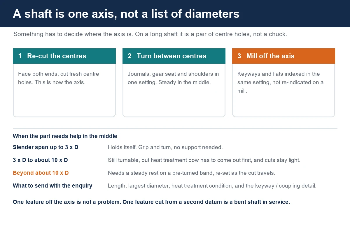
Second, the finishing operation has to be able to get the part straight before it starts cutting sizes, and that means turning between centres rather than gripping a chuck. A three-jaw chuck grips on a heat-treated, slightly bent surface and reproduces the bend. A pair of centre holes, re-cut after heat treatment, give the part a fresh axis that is independent of whatever it did in the quench.
Where a customer wants a hardened and ground surface, the same logic applies one step further out: the turning operation leaves the stock the grinding operation needs, and the turning route has to leave the part straight enough that grinding can find it. We went through the related problem of turning a part to a finish without a grinding operation in our expansion sleeve case study, and the underlying discipline is the same.
The two setups
The route that settled this job was two setups, both on a slant bed lathe, and the customer's own shop had been using three.
Setup one took the rough, heat-treated blank and put it between centres, with a driving dog at one end, and faced both ends and re-cut both centre holes. This is the operation that decides the job, and it is the one that is easiest to rush. Re-cutting the centre holes is not a formality: it removes the marks left by the quench, it puts a fresh cone in each end, and it means the axis the shaft is subsequently turned on is a new one rather than the axis the heat treater left behind.
Setup two turned the shaft between centres, tailstock at one end and the headstock centre at the other, with a steady rest supporting the middle. All of the working diameters, the shoulders, the gear seat and the bearing journals were cut in this one setup, from the drive end towards the tailstock. Because the part never came out of the machine between the first diameter and the last, the concentricity of the journals and the gear seat came off the machine's own geometry instead of off somebody's ability to re-chuck the part accurately.
The third setup in the old route existed for the keyways. That is where the change was made, and it is the part of this job worth explaining.
Supporting the middle without leaving a mark
A steady rest is the standard answer to a slender shaft, and it is also the standard way to make a mess of one.
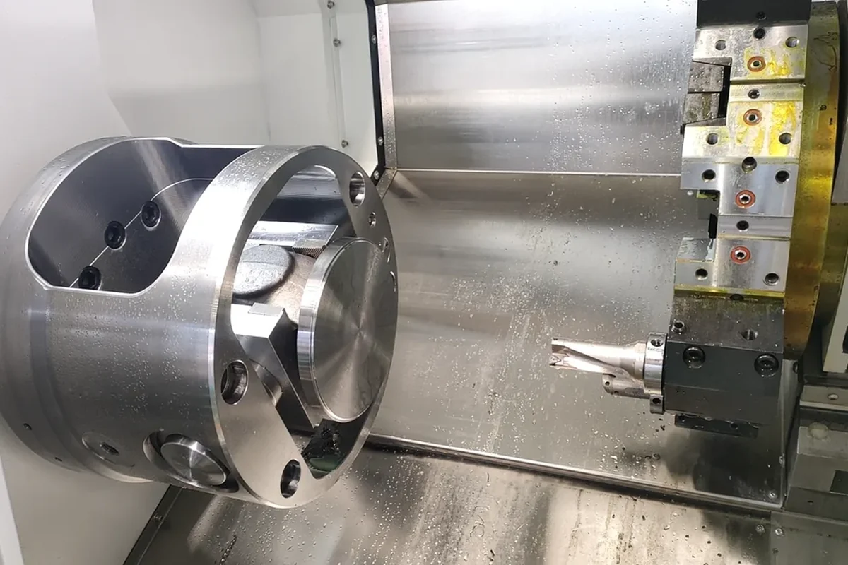
The jaws of a steady rest sit on the diameter of the part and hold it against the cutting force. If the jaws run on a raw forged or heat-treated surface, they will polish that surface, pick up grit, and press a witness mark into the shaft that has to be turned away later. If they are set too loose, the part rattles; too tight, and the part is squeezed into a triangle between three jaws.
Three things made the steady work here:
- A pre-turned band. Before the steady was brought in, a short length of the shaft where the jaws would sit was turned to a clean diameter, in the same setting, so the jaws ran on a surface that was already true to the axis rather than on the blank.
- Jaws that matched the part. Bronze or roller jaws on a steel shaft rather than hard jaws on a hard surface, and a light touch on the adjustment rather than a firm one.
- Positioning the steady where the part wanted to bend. That is near the middle for a shaft with the tool working along its length, but it moves towards the tailstock as the cut travels, because the unsupported length grows. On this job the steady was re-set once, part way through the finish pass, and the difference showed up in the diameters rather than in the appearance.
The same thinking, in a different shape, is what governs a thin-wall part in a chuck, which we covered in CNC machining thin-wall parts: the answer is never to hold the part harder, it is to hold it where it can take it.
Keyways, threads and flats
The non-round features are where the old route lost its third setup, and where the machine choice changed.
A keyway is a milled slot that has to be parallel to the axis and positioned at a known angle relative to the gear seat and the coupling end. Cut on a milling machine, that means the shaft is moved to another machine, clamped in a vice or on V-blocks, indicated in, and cut. Each of those steps is a chance to lose the angular position, and indicating a 700 mm shaft so that its slot lines up with its own keyway at the other end is slow work that a shop does not want to repeat every part in a batch.
The answer on this job was a lathe with driven tools and a Y axis. On a machine like the TCK6050Y, the shaft stays between centres with the steady in place, and the keyway is milled in the same setting as the diameters, indexed off the spindle. The angular relationship between the two keyways and the gear seat is then a function of the machine's indexing rather than of how well somebody indicated a vice. The TCK3100LY does the same job for shafts up to a metre that need a larger swing and a bigger bore, with a Y travel that covers off-centre features without a second machine.
The thread at the retaining-nut end is a straightforward turning operation, but it has one rule worth writing down: cut it in the same setting as the journal it sits next to. A thread that is lapped half a turn off the journal axis pulls the nut and the bearing slightly sideways when it is tightened, and on a shaft that carries a preloaded bearing that is enough to change the way the assembly feels.
The general question of when a turning machine with driven tools replaces a lathe plus a mill is the subject of its own article, CNC lathe vs CNC mill-turn. The short version for a shaft is that the decision is made by how many features sit off the axis and how tight their relationship to the turned diameters has to be, not by how many of them there are.
Keeping a batch on the same centreline
The first shaft is a machining problem. The fortieth shaft is a consistency problem, and on a reducer shaft batch the drift shows up in three places.
The first is the centre holes. A centre drill that is dull or running slightly off will cut a cone that is not concentric with the outside of the blank, and every diameter turned afterwards is a copy of that error. Changing the centre drill on a count rather than on a feeling, and facing the ends before drilling rather than drilling into a sawn face, is what keeps a batch aligned with itself.
The second is the steady rest jaws. They wear, and a worn set of jaws lets the part sit a little lower in the rest than the shaft before it. The visible symptom is a batch of shafts with a very slight taper towards the tailstock that grows over a hundred parts. Checking the jaws against a known diameter, and dressing or replacing them, costs minutes and saves a batch.
The third is thermal. A lathe that has been running for four hours is not the same machine as one that started cold, and on a long finish pass the difference goes into the diameters. On shafts where the customer checks the whole batch against one reference, we rough in the morning and finish after the machine has been running, so the finishing cuts are all taken on a machine in the same condition.
None of this is exotic. It is the difference between a route that produces a part and a route that produces a batch.
Why the machine changed the answer
The customer's shaft is 700 mm long, which is shorter than it sounds when the log is written out. The reason their old route worked at all is that the machine could reach both ends without repositioning; the reason it was slow is that everything off the axis had to leave the machine.
For this part we used a TCK6350B, a heavy slant bed lathe with a 630 mm swing over the bed, up to a metre of cutting length on the long version, a 96 mm spindle bore that passes 85 mm bar, an 18.5 kW spindle and a 10 or 12 inch chuck. It has the mass under the bed to finish a 700 mm shaft without the part talking back, and the tailstock travel to cover the length with room for the steady.
Where a customer's shaft is configured one end at a time, or needs a drive feature on both ends, a dual-spindle machine is the other honest answer. The TCK6050SY carries a 67 mm bore in the first spindle and a 56 mm one in the second, which covers shafts up to roughly 45 mm bar through both, and it machines a back face without a second operation. Below that size, a shaft that fits through a TCK50 at 65 mm bore and 50 mm bar capacity is a bar job rather than a between-centres job, and the whole plan changes because the part never needs a steady at all. We compared those two routes in dual-spindle turn-mill: machining both ends in one setup.
For a genuinely long shaft, longer than a standard lathe covers without repositioning, the conversation moves to a large bore machine. The QK1322 has a 240 mm spindle bore, a 1,000 mm swing over the bed and 1,350 mm of turning length, which is the machine for heavy and long work rather than for a reducer input shaft. Knowing where the boundary sits between the two is most of what a shaft quotation is about, and we wrote about how the swing, bore and chuck numbers relate to what a part can actually be turned in CNC lathe selection: swing, bore and chuck.
What the customer measured afterwards
The customer tracked three things on the first run: setups, the number of shafts that had to be reworked after assembly, and assembly time.
Setups went from three to two. Rework after assembly went to zero across the first sixty shafts, where the previous route had produced a handful that had to be re-cut, and assembly time on the line came down because the gear and the bearings went on without the fitter having to hunt for the position that let the shaft turn freely.
The change the customer described most clearly was not a number. In their words, the shafts stopped being a part they had to check before they trusted, and became a part they could bolt on. That is what a single-datum route buys, and it is worth more than any individual dimension on the drawing.
What decides the quote on a shaft job
Four things move the price on a shaft more than anything else:
- The number of setups. A shaft that can be turned complete in one setting with a steady is a different price from one that has to leave the machine for a keyway and come back.
- Whether the part moves between machines. Every move means a re-indication, and on a long part that is time nobody sees on the drawing.
- The heat treatment route. A shaft that is turned from annealed bar in one pass is simple. A shaft that is rough turned, hardened and finish turned carries the cost of the second turning operation, and that cost is real.
- The length-to-diameter ratio of the longest unsupported span. This single number decides whether the job needs a steady rest, and a steady rest changes the cycle time on the whole part, not just on one diameter.
Send the shaft drawing, the material and its condition, and the drawing of the assembly it goes into if you have it. The shaft drawing gives us the features; the assembly tells us which journals actually carry the shaft, which shoulders actually locate something, and which diameters are only there to clear a casting. Drawings can go through our drawing upload page if email is inconvenient.
FAQ
Do you machine long shafts in one setup or two?
Two, normally, and the first one exists to re-cut the centre holes rather than to remove material. Turning a heat-treated shaft between centres from a fresh pair of centre holes is what makes the whole part straight; gripping the part in a chuck instead reproduces whatever bend the heat treatment left in it.
Can a shaft this long be turned without a steady rest?
It can be turned, but the diameters in the middle of the span will not match the ends. Past a length-to-diameter ratio of roughly ten on the unsupported span, the part starts bending away from the tool and the shop is choosing between a steady rest and a slow, light cut that still will not hold the whole length.
Should the keyway be cut on the lathe or on a milling machine?
If the machine has driven tools and a Y axis, on the lathe in the same setting as the diameters, because the angular relationship between the keyway, the gear seat and any second keyway then comes off the machine instead of off a re-indication. If the part has to go to a mill, the shaft should be set on V-blocks or a fixture and indicated against the turned surface, not against the raw blank.
How do you stop a shaft going barrelled in the middle?
By supporting it, by taking the finishing cut after the part has already been roughed once in the same setting, and by keeping the cut light enough that the part does not push away from the tool. A barrelled shaft is usually a support problem rather than a tool problem, and changing inserts will not fix it.
What do you need to quote a shaft machining job?
The shaft drawing with the material and its condition, whether it has been or will be heat treated, the finished condition of the surfaces that matter, the assembly drawing if the journals and shoulders locate anything, and the batch size. If several shafts belong to the same reducer, send them together so the datum and the setup plan can be laid out once for the family.
Shafts, gears and the housings they run in are the kind of work we do every week. If you have a shaft that will not run true, or a batch where the diameters drift towards the tailstock, send the drawing and we will come back with a route and a price. Contact Handemo CNC | Email: sales1@handemocnc.com | WhatsApp: +86 135 6320 3038