Screw Pump Rotor: Helix Milling in One Clamp
A progressive cavity pump rotor looks simple on a drawing: a round bar with a twist in it. Then the drawing arrives with a note that says the helical surface must stay true over two metres of length, and the shop that quoted it at turning rates starts losing money on the third part.
We machine these rotors for pump builders who supply wastewater plants, oil field water injection and food processing lines. The part below came to us as a family of five sizes, all stainless, all with the same problem: the helix was being cut on a milling machine after turning, and every one of them needed four setups and a straightening pass before it ran true.
This is one of our case studies, written from the shop floor. No catalogue numbers, no test-sheet figures. Just what the geometry asks for, what the old route cost, and what changed when the work moved onto a machine that can turn and mill in the same clamp.
What a Progressive Cavity Rotor Actually Is
A single screw pump moves fluid between a steel rotor and a rubber stator. The rotor is a helical screw with one lobe; the stator is the same helix with two lobes and a pitch twice as long, so the two mesh and trap sealed cavities that travel from suction to discharge as the rotor turns.
Three numbers define the part, and they define the machining problem too:
- Minor diameter — the core of the screw. This is what the rubber seals against at the throat, and it carries the whole pressure load.
- Major diameter — the crest of the lobe. On most water and wastewater rotors this is between two and three times the minor diameter.
- Pitch and lead — how far the helix advances per revolution. Long pitch rotors are used for high flow, short pitch for high pressure.
The surface between minor and major diameter is not a cylinder with a groove cut into it. It is a continuous helical flank that has to be generated, and that flank is where the money goes.
Why the Helix Is the Hard Part
Turn a shaft and the tool follows a straight line. Mill a pocket and the tool follows a path you can see. Cut a helical flank and the tool has to stay tangent to a surface that rotates as it advances, and the contact point moves across the ball nose as the lead angle changes along the flank.
Two things go wrong when that is done badly, and neither shows up until assembly:
The flank becomes a series of facets. If the tool path steps over too far, the surface is a set of flats rather than a helix. It looks fine under the shop light. It leaks when the stator squeezes against it, because the rubber cannot conform to a corner it was never moulded for.
The lead drifts. A rotor that is right at the drive end but half a degree out at the free end will bind in the stator over part of its length and leak over the rest. That is the failure mode that sends rotors back, and it is a machine-and-setup problem, not a tool problem.
The Four-Setup Route, and Where It Breaks
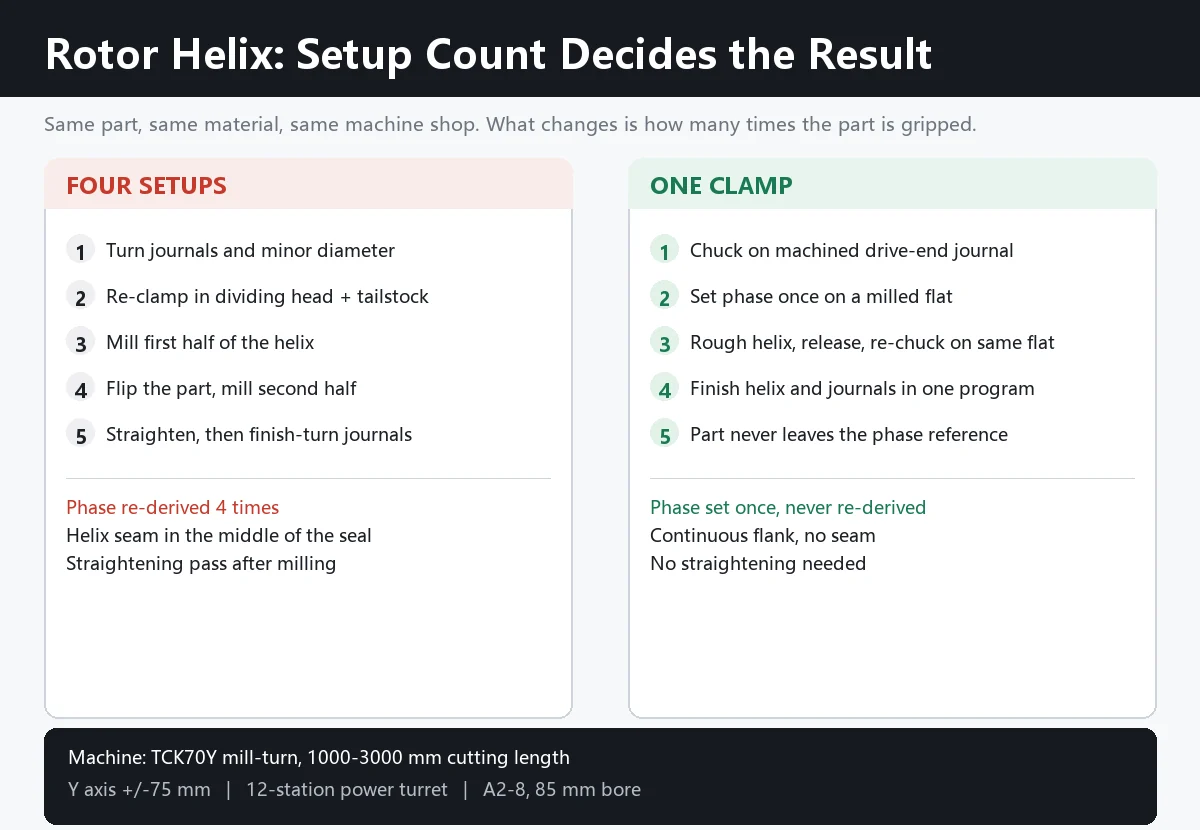
The conventional route for a rotor over about 800 mm long looks like this:
- Turn the blank between centres, rough the minor diameter, the shaft ends and the coupling thread.
- Move the part to a vertical machining centre, clamp it in a dividing head and a tailstock, and mill the helix with a ball nose in a rotary-and-linear interpolation.
- Flip the part for the second half of the helix, because the machine travel does not reach.
- Straighten, then finish-turn the journals, because the milling pass has pulled the shaft.
Each step is defensible. The problem is what the part does between them. Every re-clamp re-establishes the phase of the helix from a different datum, and phase is exactly the thing that must not move. On a 2 m rotor, a re-clamp that is out by a few minutes of arc puts the two halves of the helix out of step at the joint, and no amount of inspection catches it until the rotor is in a stator.
The flipping step is also where the length limit bites. A rotor that has to be split into two milling passes effectively has a seam in the middle of its sealing surface.
What We Changed: One Clamp, One Phase Reference
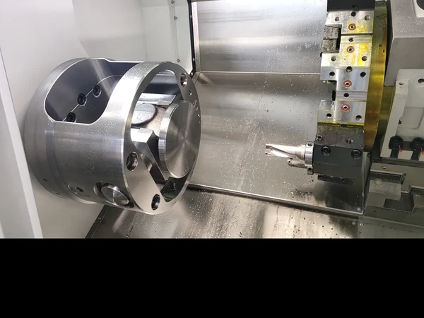
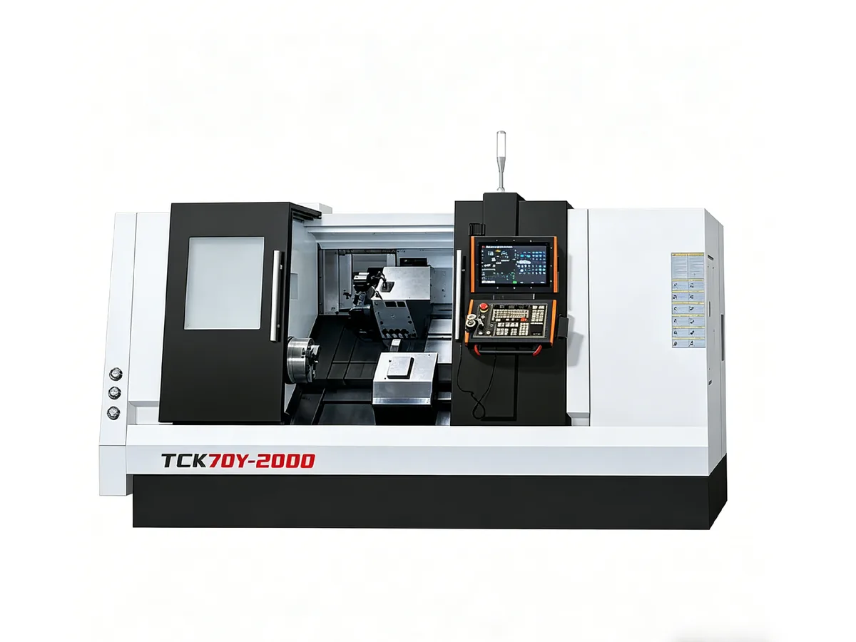
We moved the family onto a Y-axis mill-turn lathe, in this case the TCK70Y. The part is chucked on the drive-end journal, supported by a tailstock on a centre drilled in the free end, and never leaves that grip until the helix and the journals are both finished.
What that buys is not speed. It buys a single phase reference. The C axis that positions the part for the first cut is the same C axis that positions it for the last, and the Z position is measured from the same chuck face every time. The helix phase is set once, at the start, and it is never re-derived from a second fixture.
On the 70Y that is practical because the bed is available in four lengths, from 1000 mm up to 3000 mm of cutting length, all on the same 720 mm swing and 480 mm cutting diameter. One machine covers the whole family, and the operator does not relearn the setup when the part grows. For the smaller rotors in the range, the TCK56Y handles parts up to about 350 mm cutting diameter on a 65 mm bore spindle, which covers the pump and fitting work that surrounds the rotor in the same assembly.
Clamping and Datum Strategy
The machine choice is the easy half. The clamping plan is what decides whether the part comes out straight.
- Chuck on a machined journal, not on the raw bar. The drive-end journal is turned first, in the same program, and used as the grip surface. A three-jaw on black bar will not repeat.
- Tailstock pressure set low. A long slender rotor will bow under tailstock load. Set it to hold the part, not to squeeze it, and check the free end for lift before the first helix pass.
- Steady rest between the chuck and the helix start on the longer sizes. The helix cut is an interrupted cut by nature, and a part that is only supported at both ends will sing in the middle.
- Phase set on a flat, not on a jaw. We mill a small flat on the drive end and use it as the C-axis reference. Jaws move; a machined flat does not.
- Rough the helix, then stress-relieve the grip, then finish. On 316L and duplex we take the helix to a roughing allowance, release and re-chuck on the same flat, then take the finishing pass. It costs one re-clamp, and it is the only one in the process.
Cutting the Helix: Three Ways, and When Each One Makes Sense
There is more than one way to generate the flank, and the right one depends on the lead angle and the length.
Ball nose interpolation. A ball nose end mill in the live tool station, with the C axis and Z axis interpolating to follow the lead. This is the flexible option: any lead, any lobe count, and the same tool covers roughing and finishing. The cost is time, because the stepover has to stay small enough that the flank does not facet. On a long rotor that is the slowest of the three, but it needs no special tooling.
Disc milling. A disc or side-and-face cutter, set at the lead angle, ploughs the groove in one pass per lobe. Fast on a constant lead, and it leaves a clean flank. It needs a dedicated cutter per pitch, and the cutter has to be set to the lead angle precisely, so it suits a family that repeats rather than a shop that quotes one-offs.
Whirling. An external whirling head with indexable inserts, orbiting the part while the part rotates slowly. This is the production answer for long rotors: the cut is continuous, the chips clear, and the flank comes off in one engagement rather than a thousand stepovers. It needs a machine with the right head and enough Z travel, and it is worth its cost only when the batch justifies it.
On this family we run ball nose interpolation for the first-off and the small sizes, and whirling for the repeat orders above about 1.2 m. The setup, the datum and the phase reference are the same for both; only the tool station changes.
Materials, and What Each One Does to the Cut
Rotor material is chosen by the fluid, and each one behaves differently on the machine.
- 316L stainless — the default for water, wastewater and food. It work-hardens under a dull insert and it galls on the tailstock centre, so keep the centre lubricated and never let the tool rub.
- Duplex and super duplex — oil field water injection and seawater. Strong and notch sensitive. Light roughing passes, no dwell, and a rigid setup; a slender duplex rotor will deflect before it cuts.
- 17-4PH — higher strength rotors for high pressure. Machines cleanly in the annealed state, and the heat treat comes after roughing.
- Tool steel and chrome-plated carbon steel — abrasive slurries and dry-running duties. The helix is cut oversize and the chrome goes on after, which means the pre-plate geometry has to be right the first time; you cannot correct a helix through a plating tank.
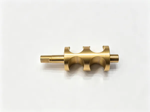
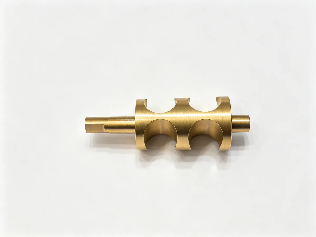
- Bronze and brass — small pumps and metering duties, and the part in the photograph at the top of this page. Free cutting, but the flank burrs at the crest and needs a light finishing pass to break the edge.
The material also decides whether the journals are turned before or after the helix. On stainless we turn the journals after the helix, because the helix pass moves the part. On bronze we do it in the same cycle, because it does not.
Inspecting a Helix Without a Gear Tester
Most pump shops do not have a lead measuring instrument, and they do not need one to catch the failures that matter.
The practical checks, in the order we run them:
- Phase at both ends. Mount the rotor between centres with a flat on the drive end against a dial indicator, and check that the crest at the free end sits at the angle the drawing predicts. This catches a drift in lead over the full length, which is the failure mode that matters.
- Major and minor diameter at three stations. Drive end, middle, free end. If the middle is small, the part bowed during the cut.
- Flank profile with a template or a profile projector. A simple template cut to the theoretical flank will show faceting immediately, and it costs nothing to make.
- Fit check against the stator. The real test. A rotor that passes the first three and binds in the stator is a rotor with the wrong lead, not a rotor with a bad surface.
We do not publish the numbers these checks are held to, because they come from the customer's stator and the duty, not from us. Send the drawing and the stator spec and the process is built around them.
Batch Consistency: The Quiet Part
The win on this job was not cycle time. It was that rotor number two runs like rotor number one, and rotor fifty runs like rotor two.
That comes from the fact that the setup does not change between parts. The same chuck, the same flat, the same tailstock pressure, the same program. There is no dividing head to dial in, no phase to re-establish, and no judgment call about whether the second half of the helix lines up. For a pump builder who assembles in the same order every week, that predictability is worth more than a faster spindle.
The same cell runs the pump shafts and the coupling parts, so the whole rotating assembly stays in one shop and one set of references. If your rotor family sits close to this one, the pump and impeller application page covers the surrounding parts, and the eccentric shaft case study covers the offset geometry that shows up on the drive end of some pump designs.
When a Mill-Turn Machine Is Not the Answer
It is worth being honest about the boundary. A Y-axis lathe earns its cost when the part is long, round, and carries features that need a second operation to reach. That is exactly a rotor.
It is the wrong purchase when the part is short and the milled features are the main event, because then a vertical machining centre with a fourth axis is cheaper and stiffer. Our lathe versus mill-turn comparison sets out where that line falls, and the stainless shaft guide covers the turning side of the same material family.
What It Means If You Buy or Machine Rotors
If you buy rotors, the question to ask your supplier is not what machine they use. It is how many times the part is re-clamped between the first cut and the last. Every re-clamp is a chance for the phase to move, and phase is the only thing about a rotor that cannot be inspected cheaply after the fact.
If you machine rotors, look at the length of your longest part and the number of setups it currently takes. When the setup count is four and the parts come in batches, the arithmetic usually favours a machine that can hold the part once. When it is a one-off per year, it usually does not.
Either way, the drawing is the place to start. Send it with the stator spec and the material, and we will tell you which route the geometry actually needs rather than which machine we would prefer to sell. Upload a drawing and you will get a process route back, not a catalogue page.
FAQ
Can a screw pump rotor be cut on a standard CNC lathe?
Only if the lathe has a C axis and live tooling, and even then the Y axis matters for the flank. A plain lathe can turn the minor diameter and the journals, but the helical flank needs the part to be positioned and interpolated, which is a mill-turn function. Some shops rough the helix on a lathe with a form tool and finish it on a mill; that works, but it reintroduces the second setup.
How long can a rotor be before the setup stops working?
It is a function of length to diameter rather than an absolute number. Beyond roughly twenty times the minor diameter, deflection and chatter become the limit rather than machine travel, and a steady rest plus a lighter roughing pass is needed. On our 70Y range the machine will take up to 3000 mm of cutting length; whether the part behaves at that length is a separate question answered by the first-off.
Do you cut the stator as well?
No. The stator is a rubber or elastomer liner bonded into a tube, and it is moulded on a core that matches the rotor. What we can do is machine the rotor to the lead and profile the stator was moulded to, and machine the tube ends and the flange faces that locate it.
What is the difference between single lobe and multi-lobe rotors?
Lobe count changes the number of starts in the helix. A single lobe rotor pairs with a two-lobe stator and is the standard for water and wastewater. Multi-lobe rotors run at lower speed for the same flow and are used where the fluid is abrasive or the pressure is high. On the machine, more lobes means more helical passes but the same datum and the same phase reference.
Can you chrome plate after machining?
Yes, and it is common on abrasive duties. The helix is cut oversize by the plating thickness and the pre-plate geometry has to be correct, because plating follows the surface rather than correcting it. We machine to the pre-plate drawing and the plater takes it from there.
Do you take small batches?
Yes. The family in this case study runs from a handful of pieces to a few hundred a year, and the first-off is quoted as a first-off rather than hidden in the batch price. If you have one rotor and a drawing, that is a normal starting point.
Talk to Us About Your Rotor
Send the drawing, the stator spec and the material, and tell us the batch size you expect in a year. We will come back with the process route, the machine the geometry needs, and an honest answer about whether the part should be turned and milled in one clamp or two.
Email sales1@handemocnc.com or message us on WhatsApp at +86 135 6320 3038. If the file is large, the drawing upload page takes STEP, IGES and PDF.