Case Study: Turning an Eccentric Shaft
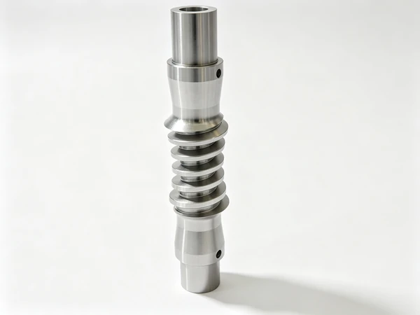
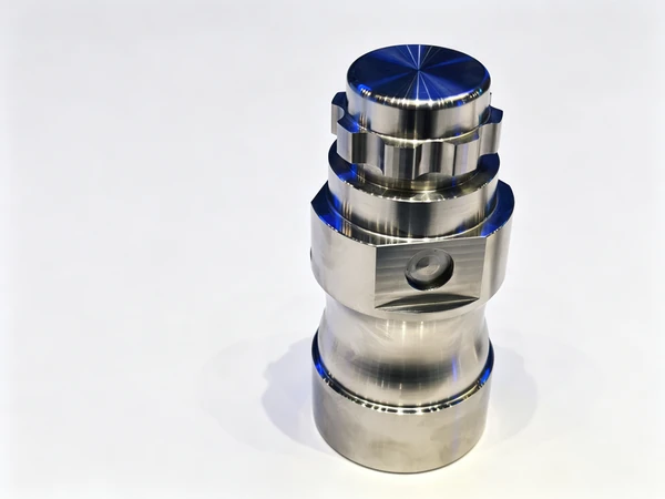
The enquiry came in with three photographs and no drawing. Two shots of the finished shaft on a bench, and one of the same shaft mounted back in the machine that had made it, with a dial indicator standing on the offset journal and the needle parked somewhere the customer did not like. The message underneath was short: the first fifty parts were fine, and then they were not. That is a very specific kind of complaint, and it almost never means the machine cannot make the part. It usually means the process can make the part once, and then something in the process moves.
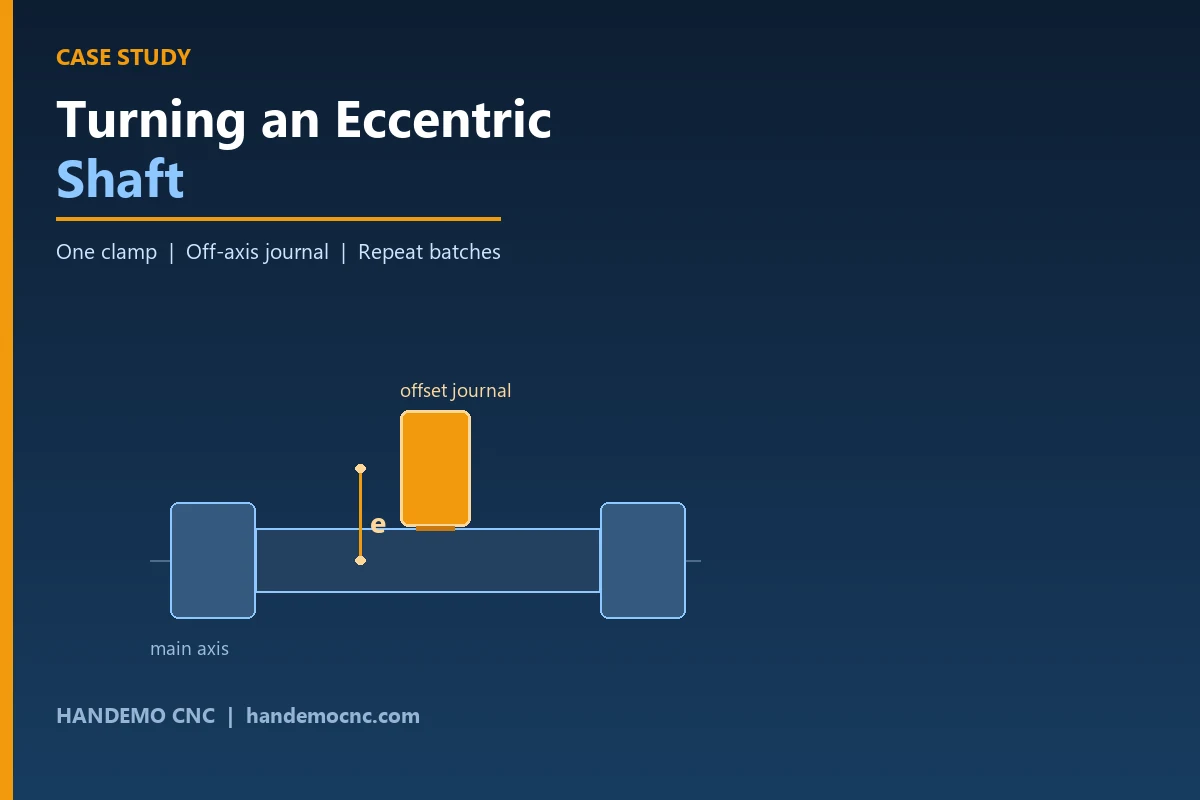
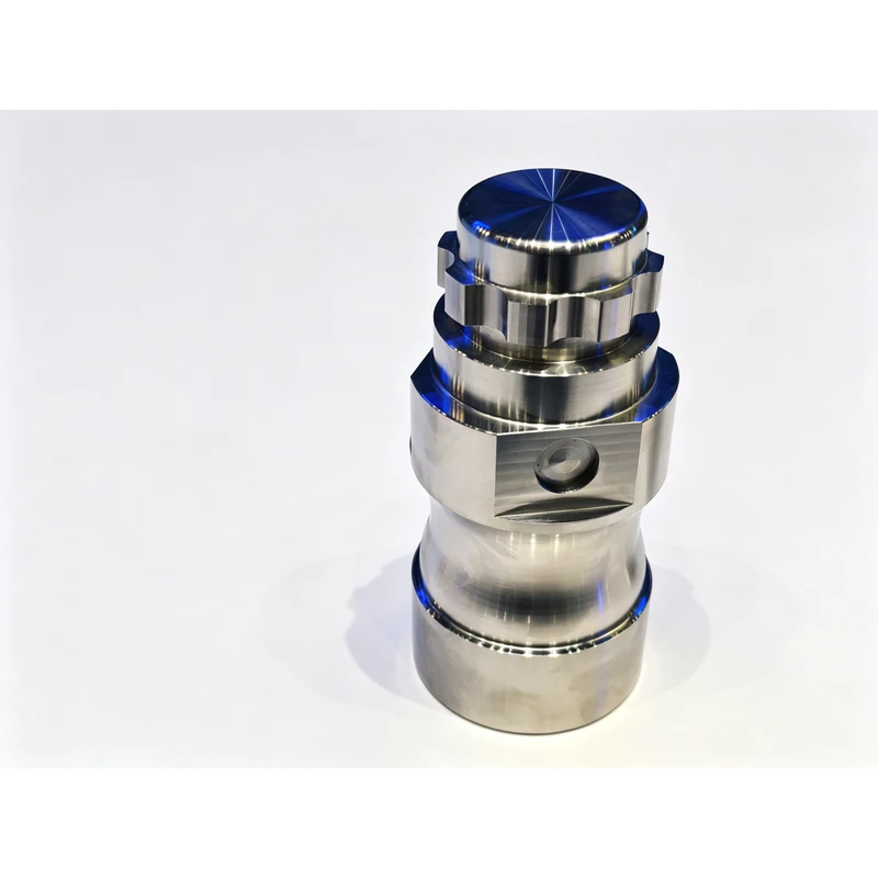
An eccentric shaft is a turned part where one journal is deliberately cut off the centre line of the rest of the shaft — an offset crank pin, a cam, an out-of-line bearing seat. Everything about the part is normal turning except that one feature, which is the only feature that decides whether the part works. The customer, an automotive components supplier, had been running it successfully on a standard slant bed lathe with an eccentric fixture. What they could not do was run it successfully for a whole batch.
What the Part Has to Do
The shaft carries the load at both ends in its main journals, and drives or is driven through the offset journal in the middle. Functionally, the offset journal has to sit in the right place around the main axis, and it has to sit in the same place in every part in the batch. Those two requirements sound like one requirement. They are not, and the difference between them is the whole project.
- The offset journal must be cut in the correct angular and radial position relative to the main journals
- The main journals must remain coaxial with each other, so the shaft fits its bearings
- The eccentricity must be the same from the first part of the batch to the last
- The transition between the main body and the offset journal must be clean enough for the fillet to survive service loads
Written on a drawing, that is a short list. On a machine running a full shift, the first line is the one that decides whether the customer is happy. If the offset drifts across a batch, the parts still measure within the drawing individually — they are just not interchangeable, and the assembly line finds out before the inspection department does.
Why the Eccentric Fixture Was Drifting
The shop was using a well-established route, and it is worth saying clearly that the route is not wrong. It works, and plenty of shops use it. A block or a fixture holds the shaft offset from the spindle centre by the eccentricity, and the offset journal is turned on that setting while the shaft turns about the offset axis. When the first part is off the machine, it looks right.
Three things then work against the shop over a batch.
The first is the fixturing itself. An eccentric block has to reproduce the offset every time it is loaded, and on a fixture that is bolted and unbolted all day, it does not. The offset is a position set by hand, and a position set by hand has a distribution around it. Small at first, wider later, and invisible on the finished part.
The second is the change of datum between operations. The main journals are cut on one setting, the offset journal on another, and the relationship between the two exists only in the fixture. If the fixture is right, the part is right. If the fixture has moved a little, the part is wrong, and there is no measurement on the machine that catches it before the part is finished.
The third is thermal movement across the shift. The customer had already raised this themselves — they wanted good cooling on the spindle, the turret and the live tooling. They had noticed that the parts drifted as the day went on, which is exactly what a shop sees when a fixture and a spindle warm up at different rates and both are being relied on to hold a position.
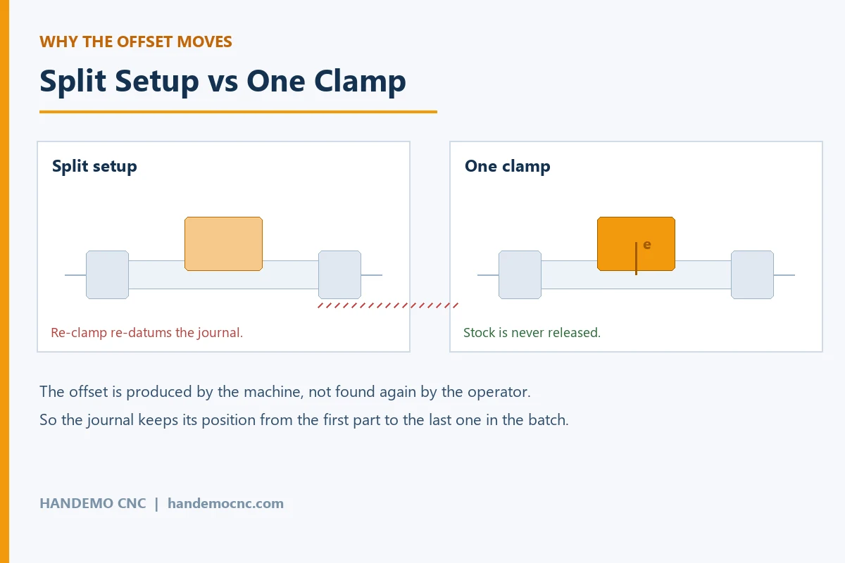
The complaint that comes back from a shop in this position is nearly always the same sentence: “the first ones were good”. That sentence is worth reading carefully. It is not a complaint about the machine’s capability. It is a complaint about a process that depends on something being set back to the same place by hand, hundreds of times, with no feedback when it is moving.
What We Did
We quoted the shaft on a Y-axis turning and milling platform instead of a plain lathe with an eccentric fixture, and that single decision carried the project.
On a machine with a Y axis and a controlled C axis, the offset does not have to be created by a fixture. The main journals are turned on the main axis in the normal way. The offset journal is then produced with the spindle indexed and the tool moved off the centre line under program control, so the eccentricity is a number in the program rather than a position under a clamp bolt. That single change removes the fixture from the accuracy chain, which is where the drift was coming from.
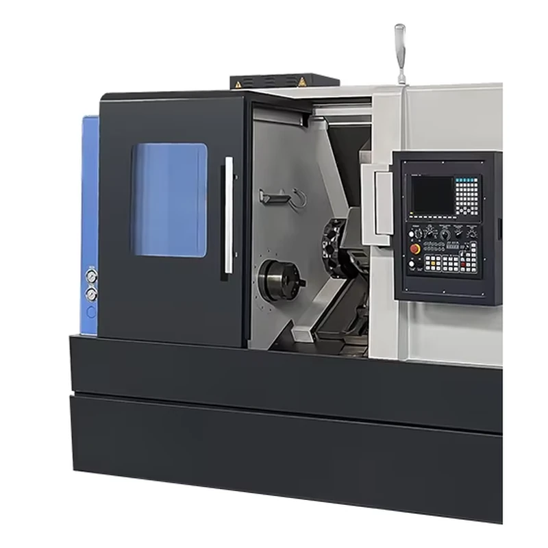
The model we put forward was the TCK2100LY CNC mill-turn machine, the Y-axis turning and milling combination in our mill-turn range. It carries a live tool turret and a Y axis on a slant bed turning structure, which is what this family of part asks for: turning for the journals, off-axis movement for the eccentric journal, and live tooling for the flats and the small cross features that usually accompany it. The part is finished without being released from the chuck between the main turning and the offset, so there is no re-datuming step for the fixture to spoil.
The sequence runs like this. The bar is faced and centred, and the first main journal is turned with the tailstock support in place. The second main journal is turned, still on the main axis. With the shaft still held, the spindle indexes and the Y axis brings the tool to the offset position, and the eccentric journal is turned about that offset centre. Any flats, keyways or cross holes that the drawing calls for are cut in the same clamping with the live tooling. Only then does the part leave the machine.
The Machines and Why
The TCK2100LY fits this shaft because the offset is produced by the machine. Where the shaft is longer or the batch smaller, and the shop is content to accept a fixture, a TCK6050 slant bed lathe with a sub-spindle will still turn this family of part and is a lower-cost quote. Where the offset journal is close to a shoulder and the part needs a second operation on the back end as well, the TCK6050SY dual-spindle mill-turn machine takes the same idea one step further and finishes both ends in one machine. For heavy or long shafts, the TCK6350B is the one we would put the work on, because the structure is the part of the machine that has to survive interrupted cuts on a big offset journal.
What we would not recommend for a part like this is a plain lathe plus a separate vertical machining centre. The split route is not wrong in principle, but on an eccentric shaft it means the offset and the main journals are made on two machines from two datums, and the relationship between them is then a fixture problem rather than a machining problem. Fixing that with better fixturing is possible. Removing it from the process is easier. Where a shop already has a vertical machining centre and wants to use it, the honest answer is that the VMC is the right machine for the milling features and the wrong place to establish the eccentricity. Read more about how the part is made in our eccentric shaft machining solutions article.
What We Put in Place to Keep It Stable
Two things beyond the choice of machine made the job repeat, and both of them are housekeeping rather than technology.
The first is cooling, which the customer had raised before we ever quoted. An eccentric journal is cut with the tool working away from the centre of rotation for part of the revolution, and the load on the insert changes through each turn. That variation puts heat into the tool and the part unevenly, and the tool that was cutting to size at eight in the morning is not cutting to the same size at two in the afternoon. We specified high-pressure coolant through the turret and the live tooling, so the cut stays cool through the shift and the tool does not grow. This is not a small detail on this part; on the customer’s own evidence it was a large part of the drift.
The second is how the shaft is held. We run the main journals in soft jaws machined to the shaft diameter rather than gripping on a raw bar surface, and we keep the grip firm but even so the shaft is not squeezed out of round. A steady rest supports the middle of a long shaft. The tailstock is used from the first pass so the shaft never runs with the free end unsupported, and it stays engaged until the offset journal is finished.
Checking the Job Without Repeating It
The useful part of the inspection plan is that it happens in the machine rather than after it. Because both ends and the offset are cut without releasing the part, the relationship the customer cares about is produced by the setup rather than measured and corrected afterwards. We prove the finished shaft on a gauge after it comes off, and we keep a first-article record for the family so a repeat batch runs against a known result instead of against a fresh assumption.
The customer’s problem, described in their own words, was that the first fifty parts were good. What had actually happened was that the process had a position in it that only held while everything stayed exactly as it was set. Moving the offset from a fixture to a program removed that position, and the batch stopped drifting.
FAQ
Can an eccentric shaft be turned without an eccentric fixture?
Yes, on a machine with a Y axis and a controlled C axis. The main journals are turned on the main axis and the offset journal is produced off the centre line under program control, so the eccentricity comes from the machine rather than from a block bolted to the chuck. The fixture route still works and is still used; it simply makes the eccentricity a setup position instead of a programmed one.
Why did the parts drift across the batch?
Because the offset was being set by hand on a fixture each time the part was loaded, and the relationship between the offset and the main journals existed only in that fixture. Small movements in the fixture, changes of datum between operations and thermal growth across the shift all add up, and none of them show on the finished part until the assembly line finds them.
Do I need a mill-turn machine for this part?
Not always. If the shaft is short and the batch is small, a lathe with a sub-spindle and a well-made eccentric fixture will do the job. The mill-turn route becomes worth its cost when the offset has to hold across a long batch, or when the same drawing also carries flats, keyways or cross holes that would otherwise mean a second machine.
How do you hold the shaft so it does not distort?
Soft jaws machined to the shaft diameter, grip pressure kept as light as the cut allows, a steady rest on long shafts and the tailstock engaged from the first pass. On a shaft with a thin section, the clamping is more likely to distort the part than the cutting force is.
What volume makes this route pay?
The route pays from the first batch where the fixture route is losing position, because the cost of a part that has to be reworked or scrapped is usually larger than the difference between the machines. We run single trial parts to prove the process and the fixture, then repeat batches on the same program. Send the drawing, the material and the annual volume and we will recommend the machine and the sequence.
Get a Quotation for Your Shaft Work
Tell us about the part — material, overall length, where the offset sits and how far off the axis it is, and the batch size — and Handemo will recommend the machine and the process and quote the tooling and workholding that makes it repeat. Contact Handemo CNC | Email: sales1@handemocnc.com | WhatsApp: +86 135 6320 3038
You can send a drawing through our drawing upload page and we will come back with a machining plan and a quotation against your part. Related reading: Case Study: Machining a Transmission Shaft and CNC Lathe vs Mill-Turn: How to Choose.