Copper Busbar Machining: Bend Order Matters
The enquiry was for busbars. Flat copper, 10 by 80 mm, a metre and a bit long, two rows of holes, some of them slotted, and a bend at each end to bring the bar down onto a terminal. The drawing was clean. The note on it said "deburr all edges". That was the whole specification.
Three weeks later the same shop sent us photographs of a stack of parts that would not assemble. Every bar was the right length. Every hole was in the right place on its own bar. Put two bars side by side in the cabinet and the hole rows walked away from each other, half a millimetre at one end, more at the other.
The bars had been machined flat, drilled and deburred, and then bent. The bend was the last operation, which is the natural order if you think of the bar as a part that gets folded at the end. It is also the order that moves the holes, because a bend does not only bend. It stretches the outside of the bar and shortens the inside, and the metal has to come from somewhere.
This is one of our machining solution notes, written from what shops send us. It is about copper busbars as a machining job rather than an electrical one: what the bar stock is like when it arrives, why the order of bending and machining decides whether the parts assemble, how to hold copper without marking it, and what changes when the bar is tinned. If you machine aluminium plate, most of it reads across, with the clamping advice being the part that changes most.
Copper Is Not Aluminium With a Different Colour
Both are soft, both cut fast, both are used for the same kind of electrical hardware, and that is where the similarity stops being useful.
Aluminium is light and springy. It cuts with a clean chip, it galls if you let the tool rub, and it moves when you take the clamps off because the internal stress from the mill was never relieved. Copper is heavy and soft in a different way. It does not spring back much, it deforms and stays deformed, and it work-hardens as you cut it. A copper chip does not break and fly away; it curls and stays curled and lies in the pocket until you flush it out.
The practical consequence is that copper is easier to cut than aluminium and harder to hold. The cut is forgiving. The clamping is not. A three-jaw chuck or a vise tightened the way you would tighten it on steel will leave a copper bar bowed, and a bowed bar machined flat becomes a straight bar with a curved hole pattern once the pressure comes off.
There is a second thing worth knowing before the first cut. Busbar copper is usually supplied hard-drawn, because hard-drawn bar is stiff and holds its shape in a cabinet, and because the electrical conductivity is not affected by the temper. Hard-drawn means work-hardened. It bends, but not indefinitely: take a hard bar around a radius that is too tight and the outside of the bend cracks, sometimes visibly, sometimes as a line of orange peel that only shows up after tinning. If the drawing calls for a tight bend, the bar you want is annealed, or the bend has to be done before the last of the hardness is used up.
The Bar You Buy Is Not Straight
Busbar arrives as a sawn length from a coil or a straight length from a mill. Neither is straight in the sense a machinist means.
A coil-sourced bar has a set: it remembers being wound. Laid on a table it will show a curve over a metre and a twist over three. A mill-length bar is better but still carries camber, and the saw cut at each end is square to the saw, not to the bar. None of this matters if you reference the machined edge. All of it matters if you push the bar against a stop and assume the stop has established an edge.
This is the same argument we make about forged blanks, and it has the same conclusion: the first operation does not use a datum from the stock, it makes one. For a busbar that usually means a light face and edge cut on one long side and one end, in a fixture that holds the bar without fighting the set, and then everything after that is measured from the cut edge rather than from the saw.
If the bars are long enough that the set is severe, the fixture has to be able to pull them straight without permanently bending them. That is a row of toe clamps along the bar, not a vise at each end. A vise at each end on a bar with a set will straighten the middle into an arc and machine that arc into the part.
Bend First, or Machine First
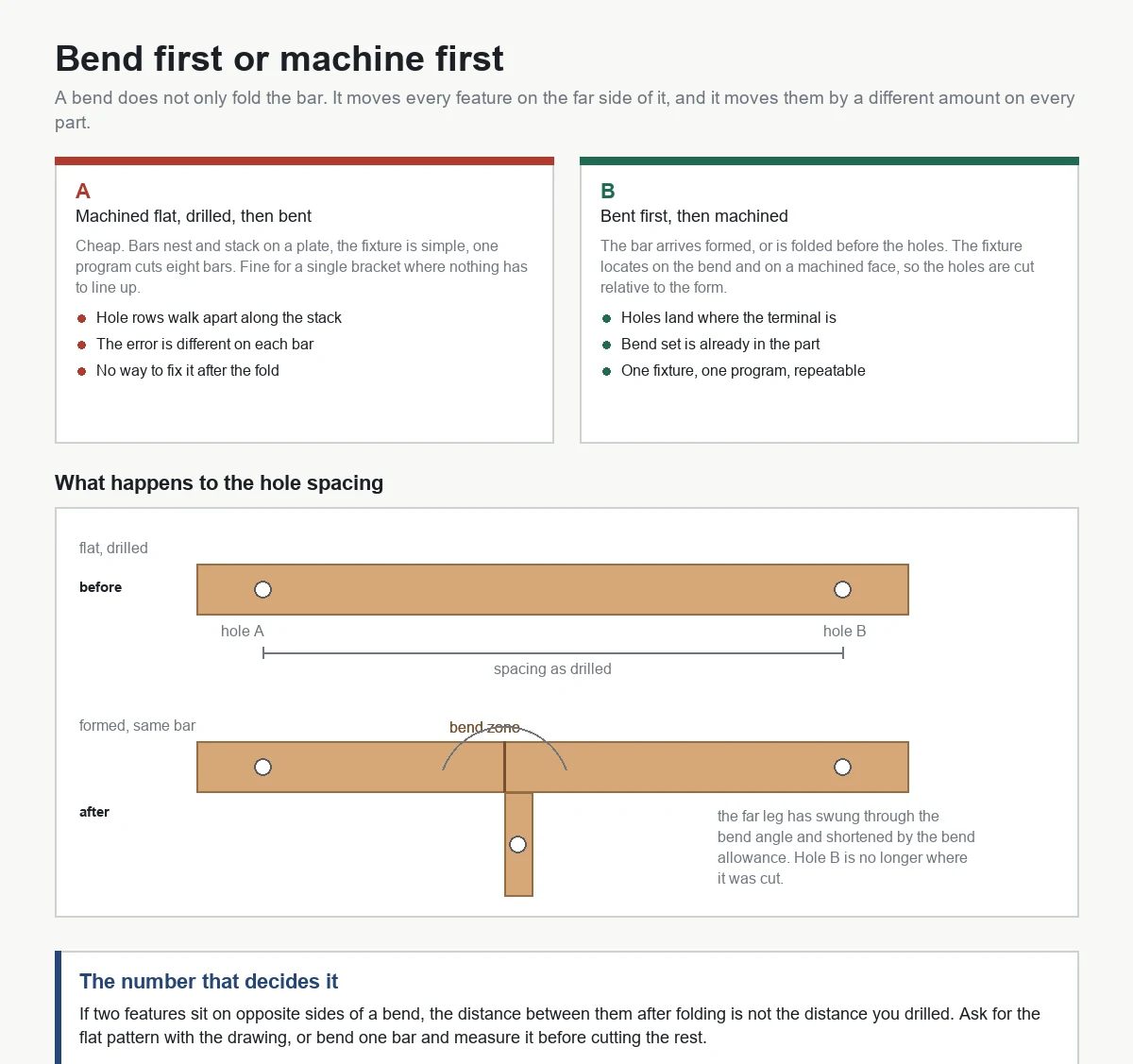
This is the decision that produced the photograph of parts that would not assemble, and it is worth being concrete about it.
When a flat bar is bent, the material on the outside of the bend is stretched and the material on the inside is compressed. Between them is a surface that keeps its original length, usually taken as a third of the thickness from the inside for a bar of this proportion. Everything on the flat part of the bar beyond the bend zone keeps its length, but its position relative to the end of the bar changes, because the end has swung through an angle and the bar has been shortened by the bend allowance.
Now put the holes in first. Hole A is 40 mm from the end, hole B is 240 mm from the end, and there is a bend between them. After the bend, the distance along the bar from A to B is not 200 mm any more. It is 200 mm minus the difference between the developed length and the formed length across the bend, and it is also rotated in space, because the section beyond the bend is no longer in the same plane as the section before it. On a single bar this is invisible. On a stack of twenty bars bolted to a common plate, it is the whole problem: each bar was bent to the same nominal angle, each bend took a slightly different amount of set, and the errors add up along the row.
The fix is not a better bend. The fix is to decide which features belong to the flat and which belong to the form, and to machine the ones that belong to the form after the form exists.
The order that works
Cut the bar to length with the bend allowance already in it. Bend. Then machine the holes, the slots and the ends, holding the bent part on the flat section in a fixture that locates on the bend itself, or on a machined face that was cut before the bend and is still flat. The holes then sit where they belong relative to the terminal they have to reach, which is the only relationship the assembly cares about.
The order that gives trouble is bend last: machine flat, drill, then fold. It is cheaper, because flat bars nest, stack and clamp easily, and it is fine for a single bar or for a bracket where nothing has to line up with anything. It is not fine for a row of bars that share a bolt pattern, and it is definitely not fine when the bend angle varies a degree or two from part to part.
The bend allowance nobody writes on the drawing
Most busbar drawings give the formed dimensions: overall length, height of the upstand, hole positions measured along the formed part. The machinist needs the flat length, and the flat length depends on the bend radius, the angle, and the tooling in the press brake. Two shops bending the same drawing on different tooling will produce flat blanks of different lengths, both correct.
The way to avoid an argument is to ask for the flat pattern with the drawing, or to bend one bar and measure it before cutting the rest. What you should not do is calculate the flat length from the formed dimensions and trust it on the first batch. The bend deduction is a property of the press brake, not of the drawing.
Hold Copper Without Marking It
Copper shows every mark. A serrated jaw leaves a row of dots that no amount of deburring removes, and on a tinned bar those dots become visible holidays in the plating. On a busbar that goes into a cabinet where someone will look at it, that is a rejected part.
Three approaches, in the order we would try them.
Soft jaws machined to the bar's width, with a shallow pocket so the bar sits in a channel rather than being pinched between two flat faces. The jaw material is aluminium or a hard plastic; the pocket carries the load sideways, so the jaw pressure can be low. This is the default for short bars and for anything with a visible face.
A fixture plate with the bar profile milled into it, toe clamps or low-profile edge clamps pushing the bar down and against a fixed edge, and the clamp screws torqued by hand rather than by feel with a long handle. On a plate you can nest six or eight bars and cut them in one cycle, which is also the cheapest way to run the job: the tool changes are shared and the loading is once per plate instead of once per bar.
Vacuum, for thin and wide busbars and for laminated stacks, where any clamp on the top face is in the way. It needs a good flat seat and a gasket pattern that follows the part, and it will not hold a bar with a set in it, so the bar has to be flattened first.
What all three have in common is that the clamping force is mostly sideways and downward, not across the thickness. Copper is soft enough that a vise closing on the 10 mm edge of a 10 by 80 bar will bow the bar between the jaws if the jaws are at the ends, and will mark it if they are in the middle.
Drilling, Deburring and the Burr Nobody Sees
Copper drills easily and burrs badly. The burr does not break off like a steel burr; it smears and folds over, and on the exit side of a through hole it folds into a lip that is thicker than the wall of the hole.
Two things help. Drill with a sharp, polished, high-helix tool and enough feed that the edge cuts instead of rubbing; a dull drill on copper work-hardens the surface and then skates. And break the exit with a backer: a sacrificial aluminium or hard-plastic plate under the bar turns a folded lip into a clean break, at the cost of one more thing to clamp.
Deburring by hand with a file is what most shops do and it is where the inconsistency comes in. A bar deburred by three different people has three different edge breaks, and on a slotted hole the corner is where the file catches and gouges. A brush head or an orbital deburring tool on the same machine, run as a second operation after the drills, gives the same edge every time. If the bar is going to be tinned, the edge break matters more than it looks, because plating builds on a sharp edge and thins on a rounded one.
The burr that gets missed is inside a cross hole: a hole drilled into the side of a bar intersects the hole drilled through the face, and the intersection has a burr on both sides that no file reaches. A flow-through deburr, or a second pass with a ball tool, is the only way to clear it. If the bar carries current, that burr is a hot spot; if it carries a bolt, it is a false torque reading.
Tinning Changes the Part
Most busbars are tinned, silver-plated or left bare with a protective coating. Whichever it is, it happens after machining, and it changes the dimensions you just cut.
Hot-dip tinning adds a layer that is thickest at the edges and in the holes, because the tin drains and pools. Electro-tin is more even but still builds on the edges. Either way, a slot cut to the drawing is smaller after tinning, and a hole that was a comfortable fit for a bolt becomes a tapping fit. The usual answer is to cut the holes at the top of the range and let the plating bring them back, and to mask anything that has to stay bare.
The other change is cosmetic and more expensive. Copper that has been handled, cooled with the wrong coolant and left damp will stain, and the stain does not plate over. Sulphur and chlorine in cutting fluid attack copper; a fluid that has been fine on steel for a year can leave green marks on a copper bar in a week. Use a fluid intended for copper or a clean synthetic, wash the parts, dry them, and do not leave them in a basket over a weekend.
Chips, Coolant and the Pocket That Fills Up
Copper makes a lot of chip for the volume of metal removed, and the chip is heavy. In a pocket, a slot or a nested plate, the chips pack rather than scatter, and a packed pocket is how a bar gets pushed up off its seat mid-cut.
Air blast is more useful than flood on this job: it clears the pocket, it does not stain, and it does not need to be separated from the chip later. Where flood is needed for the drill, aim it at the hole and let the air do the clearing. Program the tool path so that each pocket is cut from the inside out, and add a retract and a blow between pockets rather than relying on the coolant to wash the chips out of a corner it cannot reach.
One more: copper conducts heat away from the cut very well, so the tool tip runs cooler than it would in steel and the chip carries most of the heat. That sounds like good news and it mostly is. The catch is that a cool tip with a soft material is exactly the condition for built-up edge, so the surface finish falls apart before the tool looks worn. If the finish goes dull halfway through a batch, change the insert; do not chase it with speed.
Which Machine, and Why the Table Matters More Than the Spindle
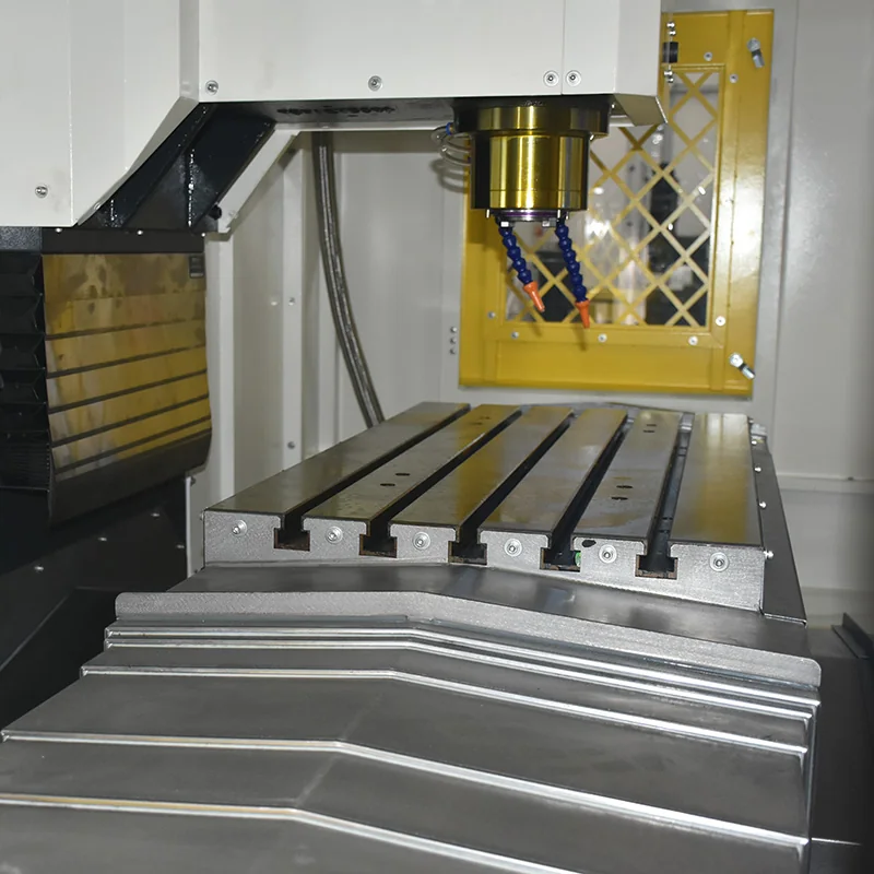
Busbar is a flat part with a long footprint, and that makes the table the first specification to check, not the spindle speed. A 2 m bar cannot be machined on a machine with 800 mm of travel unless it is done in two setups, and two setups on a bar with a set in it is how the hole pattern ends up stepped.
| Machine | Table and travels | Why it fits busbar work |
|---|---|---|
| VMC855 | 1000 x 550 mm table, 600 kg load, 800 / 550 / 550 mm travels, BT40, 8000 rpm | The short-bar machine. Bars up to about 900 mm with the ends inside the travel, nested six or eight to a plate. The 550 mm of Y is what limits how many rows you can nest, not the X travel. |
| VMC1160 | 1200 x 600 mm table, 800 kg load, 1100 / 600 / 600 mm travels, BT40, 8000 rpm | The step up for metre-long bars: 100 mm more in X and 50 mm more in Y than the 855, which is often exactly the difference between four bars per plate and six. Same BT40 tooling, so the fixture and the programs carry over. |
| VMC1560 | 2200 x 600 mm table, 1500 kg load, 1500 / 650 / 650 mm travels, BT40 | The long-bar machine. A 2 m table takes the full bar in one setup, which is the only way to keep the hole rows parallel along the length. The 1500 kg rating matters because a plate full of copper is heavy. |
| VMC1690 | 1600 x 800 mm table, 1500 kg load, 1600 / 900 / 700 mm travels, BT50, 6000 rpm | For thick bar, wide plate and busbar assemblies that arrive as a weldment. The BT50 spindle is about the heavier cut and the larger tool, not about speed; copper does not need spindle speed, it needs a rigid machine and a clear pocket. |
Two notes on that table. The load rating is not a formality on this job, because a 2200 by 600 mm plate carrying eight 10 by 80 mm copper bars plus the fixture is heavier than the same plate carrying aluminium, and the machine has to accelerate it without the servo lagging. And if the bars have bends at both ends and holes on more than one face, the question stops being a VMC question: a horizontal machine with a tombstone lets you do two or three faces in one clamp, and for a family of busbars that is usually cheaper than a second and third setup on a vertical.
Where the bend is done on a press brake in the same shop, the machine choice also decides the order of operations. If the bars are going to be bent after machining, they have to be machined as flat bars on a plate, and the fixture has to be able to hold a flat bar that is not straight. If they are bent first, the fixture has to hold a formed part, and that is a different plate and a different program. Decide before you quote, not after.
What to Send With a Busbar Enquiry
The formed drawing, the flat pattern if you have it, the temper of the bar, the finish, and the quantity per month. Of those, the temper is the one that is most often missing and most often the reason a quote comes back with a caveat: hard-drawn bar and a tight bend radius are a conversation about cracking, and the answer may be a different temper rather than a different machine.
If the bars are part of an assembly, send the assembly drawing too. The hole that matters may not be the one with the tightest position on the part drawing; it may be the one that has to line up with the terminal in the cabinet, and only the assembly drawing shows that.
Questions We Get About Copper Busbars
Should I machine the bar before or after bending?
Bend first for anything that has to assemble with other parts, then machine the holes and slots from the bent form. Machining flat and bending afterwards is cheaper and is fine for single parts, but the bend zone changes the distance between features across it, and the error varies from part to part with the bend set.
Why do my holes come out oval?
Usually because the bar moved during the cut, or because the drill entered on a slope. Copper is soft enough that a bar held only at the ends will lift in the middle under drill thrust. Clamp along the length, use a stub drill for the first hit, and check that the bar is seated before the cycle starts rather than after.
Can I cut copper with the same tools I use on steel?
You can, and you will get a worse finish and a shorter edge life. Copper wants a sharp, polished, high-rake tool with a smooth flute; a general-purpose steel insert with a honed edge rubs and work-hardens the surface. Keep a set of inserts for copper and do not mix them with the steel ones.
Why does the bar stain after machining?
Cutting fluid with sulphur or chlorine in it, or water left on the part. Copper reacts with both and the result is a green or brown film that plating will not cover. Use a fluid intended for copper, rinse and dry the parts, and do not store them damp.
How much does tinning change the hole size?
Enough to matter on a fitted bolt and not enough to matter on a clearance hole. The build is concentrated at edges and inside holes, so if the bolt fit is critical, cut the hole at the top of its range and let the plating bring it in, or mask the hole.
Is a router or a machining center the right machine for busbars?
A router is faster on thin flat bar with a lot of holes and no bends, and it is the right answer for a shop doing nothing but that. A machining center is the right answer when the same shop also does the bent bar, the tapped insert, the counterbore and the assembly plate, because one machine does all of it and the fixture can be a plate rather than a vacuum bed.
What is the cheapest way to run a batch of 200 bars?
A nesting plate: eight or ten bars clamped in a machined pocket, all the holes and slots cut in one cycle, and the deburring brush run as the last tool on the same machine. The savings are not in the cutting, they are in the loading, which happens once per plate instead of once per bar. We costed that arithmetic on a small-part job in a separate case note, and the same logic applies here.
Talk to Us About Your Bar
Send us the formed drawing, the flat pattern if you have one, the bar size and temper, and the finish. If the bars are part of an assembly, send that drawing too, because the hole that decides whether the parts go together is usually the one measured from the terminal rather than from the end of the bar. Email sales1@handemocnc.com, message WhatsApp +86 135 6320 3038, or put the drawing through our drawing upload page and we will come back with the operation order and the machine we would put it on.