Hydraulic Valve Machining: A Practical Guide
Hydraulic valve machining is unforgiving work. A hydraulic valve body is the one part that decides whether a hydraulic system works quietly or leaks in service. It is a block that routes pressurised oil between ports, and every feature on it exists to move fluid from one place to another at the right angle. The machining is not difficult in the way a five-axis aerofoil is difficult. It is difficult because the tolerances are cumulative: a port that is right on its own can still be wrong when it is compared with the passage it has to meet.
This guide covers what a valve body has to hold, the materials it is usually made from, how the setups are planned, what the port and sealing-face operations actually involve, and the machines that suit the work. It is written for people who already machine hydraulic parts and for buyers comparing shops.
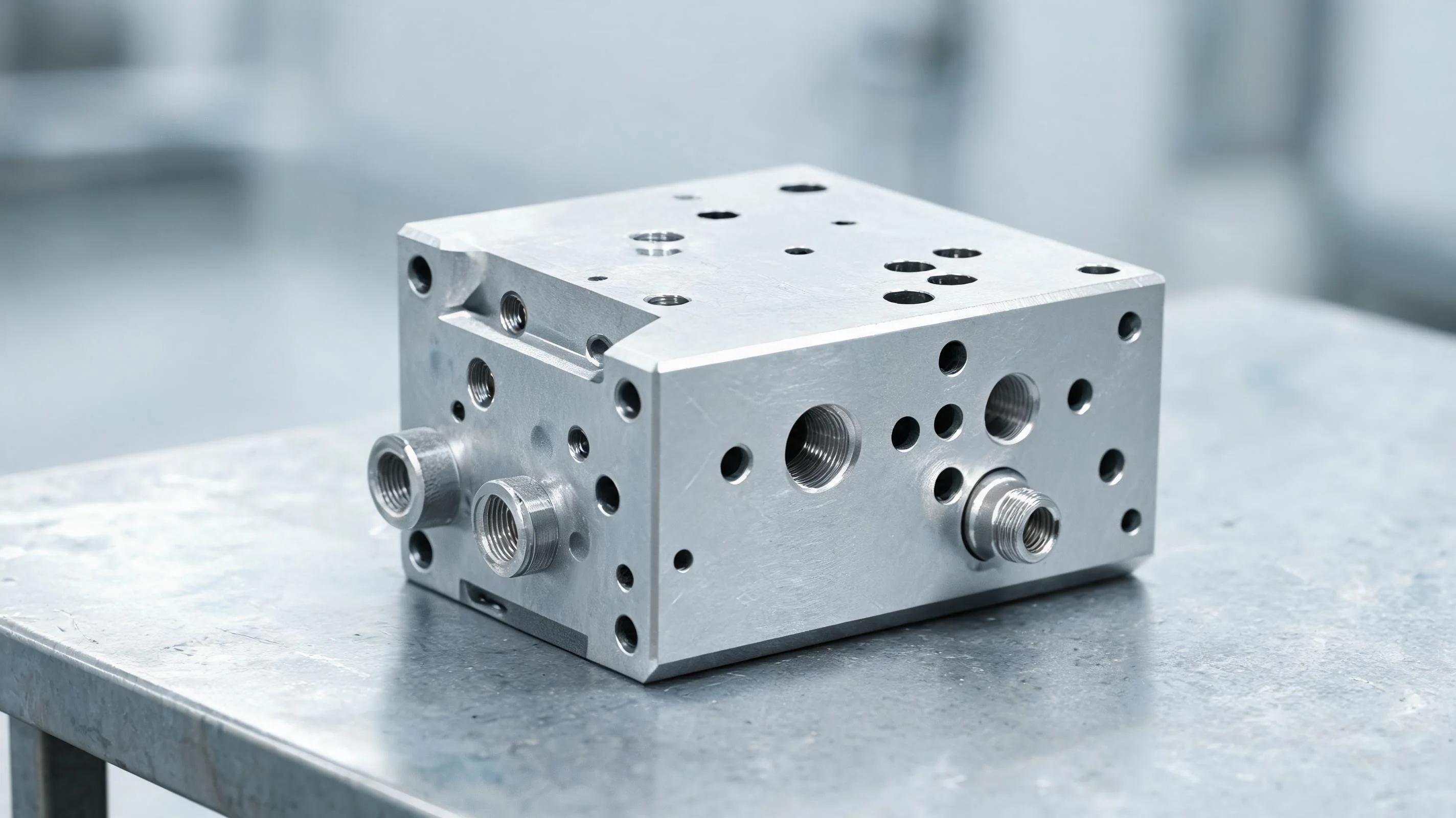
What Counts as a Valve Body
The name covers a wider range of parts than most people expect, and the machining plan changes with the type.
- A two-port block is the simplest form: one inlet, one outlet, a spool bore between them. It is often the first hydraulic part a shop takes on.
- A sectional or spool valve body carries a long, closely toleranced bore and a set of radial ports feeding it. The bore is the part that matters.
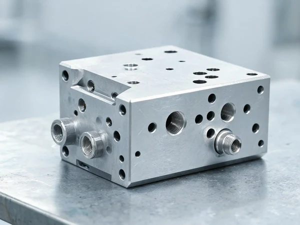
- A manifold routes many passages through one block. There may be no moving part inside it at all; its whole job is to connect ports correctly.
- A cartridge or logic body is machined to accept a screw-in cartridge, so the cavity dimensions and the sealing surface are the critical features.
- A valve block with a machined face is a body that bolts against another part, so the mating face, bolt pattern and O-ring groove all have to land together.
Whatever the type, valve body machining comes down to the same three features: where the ports are, how well the sealing faces seal, and how clean the internal passages are. A shop that gets those three right can take on any of the forms above; a shop that treats the block as a general milling job will not.
What the Machining Has to Hold
Valve bodies are rarely held to tight tolerances everywhere. The tolerances are concentrated in a few places, and the rest of the part is ordinary.
Port position is the first. A port has to meet its passage at the right place and the right angle so the flow is smooth and the wall thickness around it stays sound. Where several ports feed one bore, the spacing between them sets the timing of the valve, and that spacing is what the operator checks.
The sealing faces are the second. A machined face that bolts against another part has to be flat and clean enough for its seal to work. A scratch, a burr at the edge of a port, or a finish that is too coarse will leak under pressure even though the dimensions are correct. On a manifold the bolting face may also be the face that carries the O-ring grooves, so hydraulic manifold machining usually finishes the groove and the mating face in the same setup.
The bore is the third, where there is one. A spool bore has to be round, straight and uniform, because the spool has to slide in it with a fine clearance and no binding. This is where a valve body becomes a precision part.
Materials
Cast aluminium and ductile iron cover most valve bodies. Aluminium castings machine easily and keep the part light, but they are less stiff, so clamping pressure has to be watched or the bore will come out out-of-round. Ductile iron is used where the body has to take higher pressure; it machines well but the casting skin is abrasive and the first cut through it wears tools.
Steel bodies appear in high-pressure and mobile equipment, and they are the hardest of the common materials to machine because the passages are deep and the material work-hardens. Brass and bronze are used in smaller and marine hydraulic parts, where the material gives good sealing behaviour but galls if the tool rubs instead of cutting.
Why the Setups Decide the Job
A valve body has features on several faces. Ports come in from the sides, a spool bore runs through the length, a mounting face sits on one side and tapped ports on another. Getting all of that to agree is a question of datums, not of cutting speed.
The rule that keeps a batch repeatable is to choose the machined face that carries the most important features as the datum, machine every other feature from it, and never re-establish the datum from a raw casting surface. A casting skin moves from part to part; a machined face does not. Where the part has to be turned over, the second setup is located against a machined feature from the first, so the two setups are tied together instead of standing on their own.
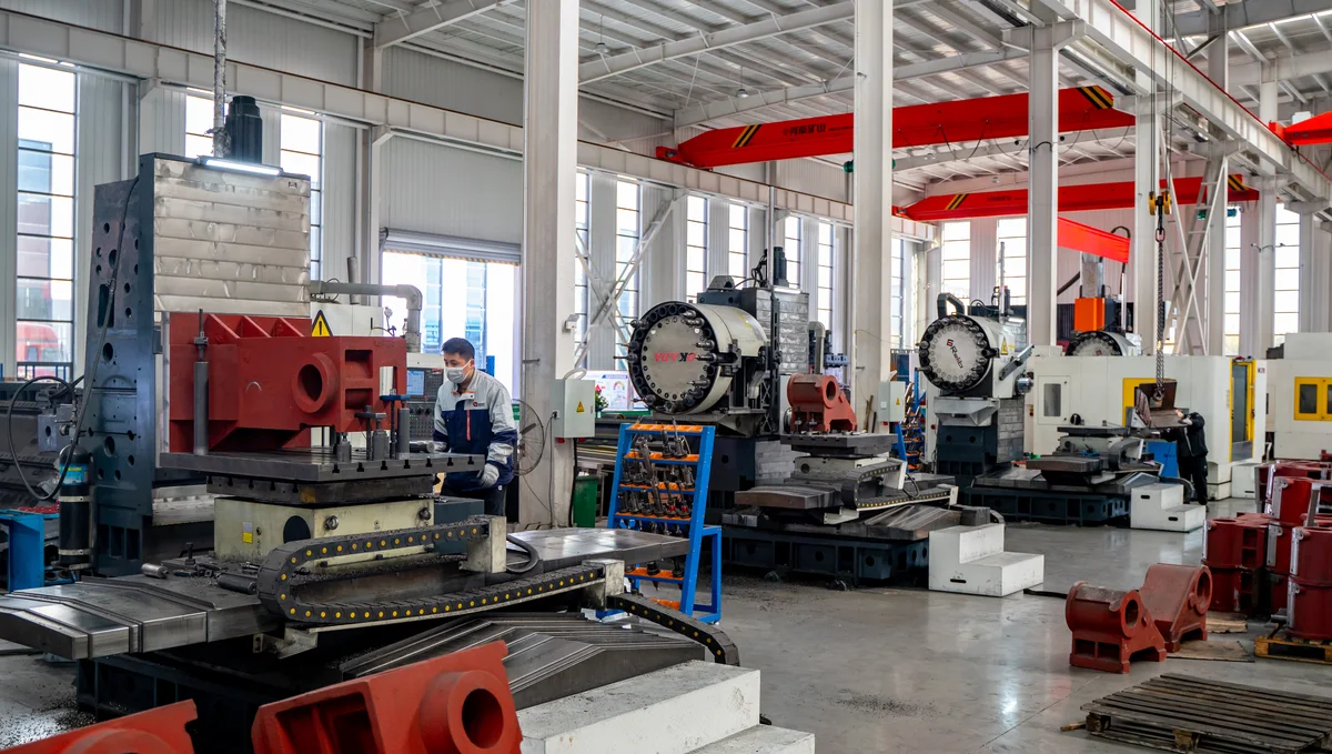
This is also where the choice between a vertical and a horizontal machine is made. A valve body worked from above needs one setup per face. A valve body with ports on four sides is presented to the spindle from several directions on a horizontal machine with a rotary table, and the part is not re-clamped between them.
Machining the Ports
The ports are the operation people remember, because they are where valve bodies go wrong. A through port is drilled and then usually reamed or bored to size, because a drilled hole is rarely round enough or straight enough for a port that has to seal or carry a spool. A tapped port is drilled, chamfered and tapped, and the chamfer has to be there so the fitting seats.
An angled port is the awkward one. It arrives at the wall at an angle, so the tool starts on a sloped surface and tends to walk before it bites. Spotting the position first, or milling a small flat where the drill starts, keeps the port where it was drawn. In ductile iron and steel the drill also has to be kept sharp, because a dull drill pushes the material instead of cutting it and the hole drifts.
Radial ports that feed a central bore need care in both directions: they have to be drilled to meet the bore without breaking through the far wall, and the intersection itself has to be deburred without changing the bore it meets.
Finishing the Sealing Faces
Sealing faces are finished last, after the part has settled. They are usually milled in one pass over the whole face rather than in overlapping passes, because a face cut in two passes can leave a step that no seal will tolerate. The insert has to be sharp and the feed consistent, so the surface has an even texture rather than a series of marks that vary across the face.
An O-ring groove or a port counterbore is finished on the same setup as the face it sits in, so the groove and the face are related to each other. A groove cut in a second setup is a groove that can be offset from the face it seals against, and the leak that follows is hard to find and easy to avoid.
Why Chip Control Matters More Here Than Almost Anywhere
A hydraulic body is full of internal passages that no eye and no brush reaches easily. A chip left in a passage will find its way into a valve, a pump or a cylinder, and the failure it causes will be blamed on something else. Chip control on valve bodies is therefore not a tidiness question; it is a functional requirement.
The practical points are straightforward. Cut the ports in an order that pushes chips out of the part rather than into a blind passage. Break the chip deliberately, with the right feed and with coolant aimed to flush the hole as it is drilled. Blow and wash the part after the last operation, and inspect the passages with a light before the part leaves the machine, because after it leaves, nobody can.
Machining Large Valve Bodies
Big valve body machining is a different problem from the small blocks most shops start on, and it fails in different ways. Once a body passes roughly 400 mm on its longest side, three things change: the part becomes heavy enough that handling and clamping affect the geometry, the wall sections are usually thicker so the material removal is much larger, and the bore lengths grow to the point where tool deflection starts to show in the result.
The first consequence is fixture design. A large body cannot be clamped on four sides without the clamps fighting the surfaces that have to be machined. The usual answer is a tombstone or a dedicated fixture that locates on two machined datums and clamps on the third, leaving the working faces clear. On a horizontal machine the fixture is also what carries the part between pallets, so its rigidity and repeatability set the floor for the whole process.
The second is stock removal. A large casting can carry several millimetres of allowance per face, and taking that in one pass loads the spindle and pushes the part away from the tool. Roughing in staged depths, with a consistent stepover, keeps the cutting force predictable and leaves enough material for a clean finishing pass. On big bodies the finishing allowance is often decided before the first cut, not after the roughing is done.
The third is bore length. A spool bore that runs 600 mm or more through a body will show taper and drift if the boring bar is unsupported for the whole depth. Line boring from both ends, or boring with a bar that is sized for the depth rather than the diameter, keeps the bore straight. Checking the bore at three points along its length — not just at the ends — is how you find the drift before the part is finished.
Large bodies are also where multi-face access pays most. If a body needs ports on four sides plus a mounting face, the setup count on a vertical machine becomes four or five operations, each with its own datum error. On a horizontal machining center with a rotary table, the same part is one setup, and the errors that would have accumulated between operations never enter the part.
For sizing, a body in the 500–800 mm class with a moderate bore depth usually lands in the HMC800-DT range; larger and heavier bodies move toward the HMC1000. Where the body is long and the bore is deep, a deep-hole boring and milling machine may fit better than a standard HMC.
The Machines That Fit Valve Bodies
Which machine is right for hydraulic valve body machining depends on how many faces carry work and how many parts are wanted.
A horizontal machining center is the natural fit for a valve body with ports on several sides and a batch to run. The part is set up once on a tombstone or a pallet, and the rotary table indexes it to present each face to the spindle, so the ports and the bores are cut without re-clamping. The 630 DT horizontal machining centers cover this class of part. The pallet change keeps the spindle cutting while the next part is loaded, which is what makes a batch economical.
A vertical machining center suits simpler bodies, or a shop that already works that way. One face per setup is the cost, but a VMC1160 can hold its own on valve bodies where the geometry does not justify a tombstone.
Where the body is essentially round - a valve with a turned spool bore and threaded ends - a CNC lathe does the turning and a mill-turn machine does the cross-ports without a second setup.
If you want the process written out for a specific part, the companion piece CNC Machining Hydraulic Valve Bodies: Process and Machines walks through it from the shop floor, and CNC Machining Hydraulic Cylinders covers the other half of a hydraulic circuit.
Frequently Asked Questions
What is hydraulic valve machining?
It is the machining of the bodies, blocks and manifolds that route fluid in a hydraulic system. Valve body machining and manifold machining are the two forms it most often takes. The work is mainly drilling and boring ports, milling sealing faces, and cutting spool bores and O-ring grooves, with the port positions and the sealing faces as the features that decide whether the part works.
What is the difference between a valve body and a manifold?
A valve body contains the moving part that controls the flow, or is machined to accept one. A manifold is usually solid inside except for its passages, and its job is to route fluid from one connection to another. Both are machined the same way, and many shops use the words loosely for the same block.
Which machine is best for machining large valve bodies?
A horizontal machining center with a rotary table and a pallet changer, because a large body has ports on several faces and the part should not be re-clamped between them. The HMC range covers these sizes. A body that has to be re-set several times on a vertical machine will lose both time and accuracy.
How do you keep the ports in the right position?
By establishing the datum on a machined face and cutting every port from it, rather than from a casting surface. Spotting each angled port before drilling, and keeping the drills sharp, stops the tool from walking off position on a sloped or interrupted surface.
Why do machined valve bodies leak at the sealing faces?
Usually because the seal's surface was not good enough or not flat enough, often after being cut in more than one pass, or because a burr was left at the edge of a port. Cutting the face in a single clean pass, and finishing the groove on the same setup as the face, removes most of the cause.
How are chips kept out of the internal passages?
By cutting in an order that pushes chips out, breaking the chip deliberately with the feed, flushing each hole with coolant as it is cut, and inspecting the passages with a light before the part leaves the machine. A hydraulic body that ships with a chip inside will fail somewhere else in the system.
Talk to Us About Your Valve Bodies
If you machine valve bodies, manifolds or other hydraulic blocks, send us the drawings and the batch size. We will suggest whether a horizontal machine, a vertical machine or a lathe suits the part, and which model in the range. Contact Handemo CNC | Email: sales1@handemocnc.com | WhatsApp: +86 135 6320 3038
If your work covers hydraulic machining more broadly — cylinders, pumps and manifolds alongside valve bodies — the same setup logic applies. Related reading: CNC Machines for Valve and Hydraulic Parts sets out the machines we build for this work, and Case Study: Hydraulic Manifold Blocks shows a manifold machined in one setup.