CNC Machining for Packaging Machinery Parts
A packaging line is judged by the hour, not by the part. Nobody at the end of the shift remembers how a filling nozzle looked on the bench. They remember whether the machine ran at rate, whether the film tracked straight, and whether the changeover at six o'clock took twenty minutes or two hours. Every one of those outcomes leads back to a handful of small machined parts that have to do the same thing at the same moment, several thousand times an hour, for years.
That is what makes packaging work different from general job shop work. The parts are rarely large and rarely complicated in shape. What they are is repetitive, and they are indexed: a star wheel, a screw, a gripper jaw or a sealing jaw has to arrive at a position at a moment, and if it arrives a little late every cycle the machine still runs, it just damages product and wears itself out. This article follows that problem through the parts, the materials, the sequence and the machines.
It sits in our application guides series, where each guide takes one industry and follows the parts from blank to finished, with the setups and machines that suit them.
The parts that come through the door
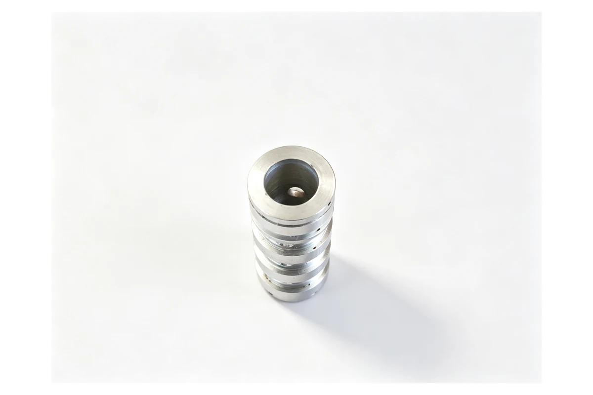
A shop supplying packaging OEMs sees a fairly predictable mix, and it splits into two groups that behave very differently on the floor.
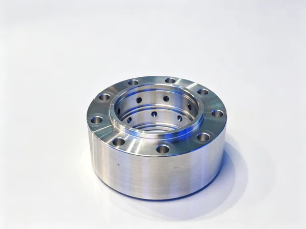
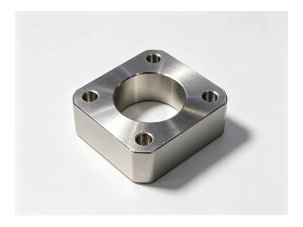
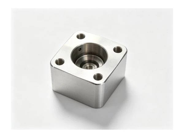
The first group is the product path: filler nozzles, dosing pistons, valve bodies and valve seats, product pump housings, manifold blocks, rotary valve discs, and the change parts that set the format. These touch the product, so they are almost always stainless, and they are usually the parts a customer asks about first because a bad one shows up as a fill weight that drifts or a drip on the seal.
The second group is the motion path: star wheels, feed screws, timing screws, gripper jaws, cam followers and cam plates, sealing jaw carriers, knife holders, film guide rollers, sprockets and drive hubs. These never touch product. They carry the package, and their whole job is to be in the right place at the right time. A star wheel pocket that is a little off does not leak. It shaves the shoulder off a bottle and sends a shower of plastic onto the line.
Between the two sits a third family that causes most of the friction in a project: the format change parts. A machine that runs three bottle sizes needs three sets of star wheels, three feed screws, three sets of gripper jaws and often three sets of filler nozzles. Those parts are low volume, they are needed on a deadline, and they have to be interchangeable with the set that is already running. It is the same problem as a mould insert, in a smaller package.
Materials, and where the cost actually goes
Product-contact parts are 316L where the product is acidic, salty or a dairy item, and 304 where it is dry goods. Both machine well if the cut is kept under the skin, and both punish a tool that rubs. The grades work harden, and a light finish pass on a work-hardened surface produces a smear that looks acceptable and fails a cleaning validation six months later.
Motion parts are a different conversation. Star wheels and feed screws are commonly 304 or a hard anodised aluminium; the anodised version is lighter and cheaper but the pocket edges wear, and on a high-speed line the wear shows up as bottle scuffing long before the part fails. Where the duty is abrasive, such as glass or abrasive-filled closures, the specification moves to a hardened stainless or a tool steel with a coating, and the machining plan has to move with it because those grades distort when they are hardened.
The material that decides the cost of a packaging job is often plastic. Many change parts, guide rails, and even star wheels for low-load lines are machined from POM, PE-UHMW or PET rather than metal. These cut easily and fast, they do not need coolant in the same way, and they produce a long stringy chip that wraps around everything. They also move after machining: a POM guide rail machined to the drawing in a warm shop can be a different length on a cold line, and a pocket cut to fit a bottle shoulder can tighten overnight. Shops that do a lot of plastic work cut the pockets slightly open and let the part settle before the finish pass, or machine them in a temperature-stable corner of the shop.
Then there is the certification side. A packaging OEM buying product-contact parts will ask for material certificates, a surface finish callout, and often a declaration that no lubricant remained on a product-contact surface. None of that changes the machining, but it changes what has to be traceable, and it is worth deciding at quotation which parts carry certificates before the first chip is cut.
Why indexing, not geometry, is the real problem
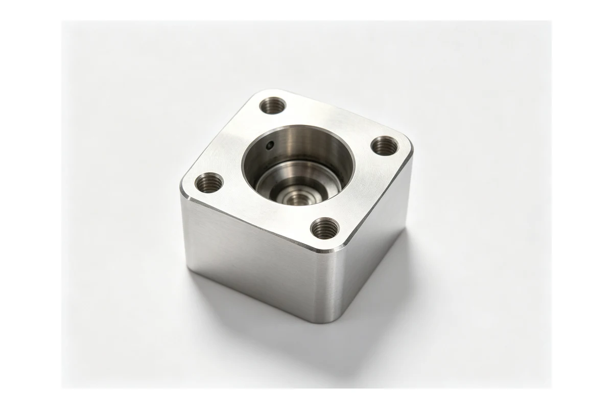
Almost every quality complaint on a packaging machine traces back to a relationship between features rather than to a feature itself. A star wheel has a pocket pattern around a bore. A feed screw has a helical groove whose pitch has to match the star wheel's pocket spacing. A sealing jaw carrier has a face that has to be square to the pivot. A cam plate has a profile that has to be centred on its mounting bore.
In each case the drawing gives the individual dimensions and leaves the relationship to a note. What actually matters on the line is the accumulated error around the circle or along the axis. A star wheel with twelve pockets, each a few hundredths off in the same direction, still measures fine on the bench and still throws bottles by the end of the shift, because the error accumulates to something the bottle can feel.
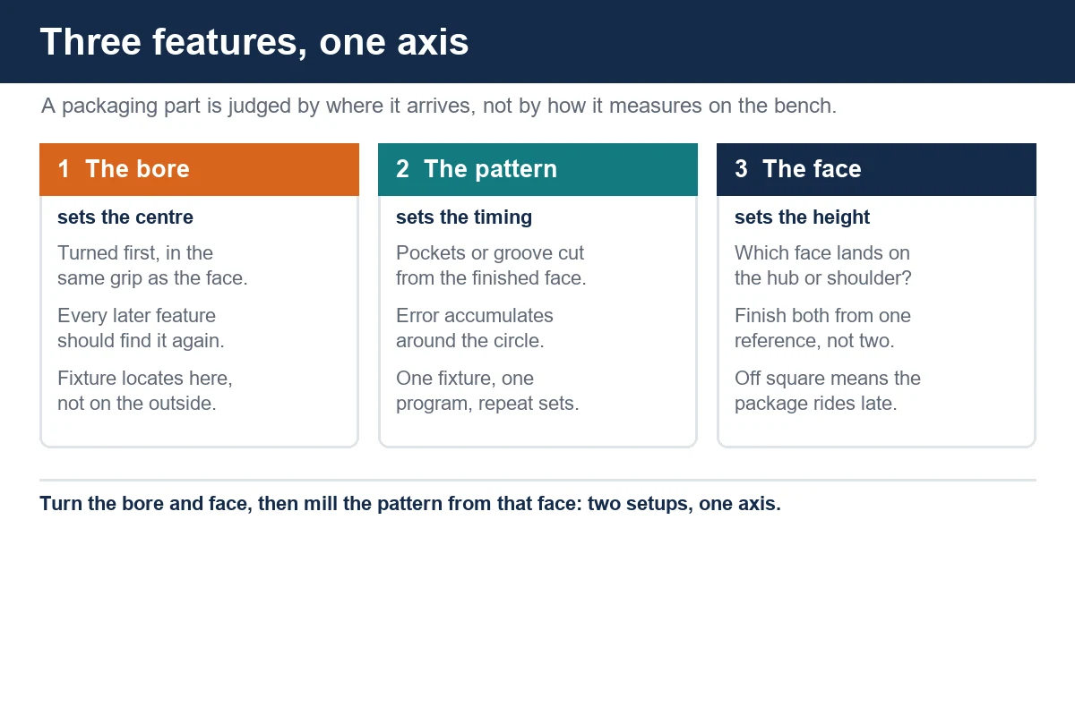
This is why the setup plan matters more than the cutting parameters on these parts. If the bore and the pocket pattern are cut in two setups, the second setup has to find the first one again, and the way it finds it decides the result. Indicating off the bore works when the bore is round and the part is stiff. Indicating off the outside diameter works when the outside is concentric to the bore, which after a turning operation it usually is. What does not work is clamping on the pocket pattern and assuming the outside is somewhere near true.
The practical answer is to keep as much of the part in one grip as the geometry allows, and to do the second operation from a face that was finished in the first. On a star wheel that means turning the bore, the front face and the outside in one setup, then milling the pockets from that finished face with the part held on a fixture that locates on the bore. The fixture does the work the indicating would otherwise do.
The sequence that works for a star wheel or feed screw
Start with the blank. For a star wheel from plate, the blank is sawn or laser cut with a margin, because the outside will be turned anyway and a laser-cut edge is not something to indicate from. For a feed screw from bar, the blank is cut long enough to hold and to sacrifice.
First operation, on the lathe: face one side, turn the outside diameter, bore or drill the centre, and turn the back face if the part is short enough to reach. Everything that defines the axis happens here. On a part with a through bore, boring from one side and then finishing from the other is a decision to make now, not later, because it changes how much material is left for the second face.
Second operation, on the vertical machining center: locate on the bore with a fixture, clamp on the finished face, and cut the pocket pattern or the helical groove. Because the part is located from the same feature the lathe used, the pattern and the bore share a centre by construction rather than by measurement.
Third operation, if the part needs it: the drive feature, keyway, cross holes, or a tapped hole pattern on the back. These are usually the features that can afford a little more tolerance, so they go last, when the part is already close to finished and the remaining risk is small.
For a feed screw the order is different in one respect: the helical groove is long, it generates heat, and it tends to push the part. Cutting it in one pass from a single setup is not realistic on most parts, so the groove is roughed in one direction and finished in the other, and the part is allowed to cool between. A feed screw that is finished hot will be a different pitch when it is cold, and the mismatch with the star wheel shows up as a bottle that rides up or lags back over the length of the screw.
Where the vertical machining center earns its place
Packaging parts are small, they come in families, and they are needed in small batches with short lead times. That combination suits a vertical machining center more than almost any other machine in a shop.
The first reason is the fixture. A star wheel, a cam plate and a gripper jaw all want to be held on a face and located on a bore or a pin, and a vertical machine with a simple plate fixture and a set of dowel pins can run all three without a dedicated tombstone. The second reason is the tool change: a pocket pattern needs a roughing tool, a finishing tool and often a small cutter for the corner radius, and having those in the magazine means the part is finished in one setup rather than three.
The third reason is access. Packaging parts are thin, and thin parts are the ones that distort when they are clamped. A vertical machine lets the operator see the part, adjust the clamp pressure, and support the underside with a sacrificial plate, which is much harder to arrange on a horizontal machine where the part sits on its side.
For the turned side of the family, a slant bed lathe does the first operation on star wheels, nozzles, pistons and rollers. A machine such as the TCK50 covers parts up to a 360 mm turning diameter with a 500 mm cutting length, a 65 mm spindle bore and a 50 mm bar capacity, which is the range most packaging change parts live in. When a part needs milling on the same cycle, such as a nozzle with a cross hole or a hub with a keyway, a mill-turn machine such as the TCK6050SY removes the second setup altogether: two spindles, a 67 mm bore on the main and a 56 mm on the sub, 50 mm bar capacity, and a Y axis of plus or minus 50 mm for the cross features.
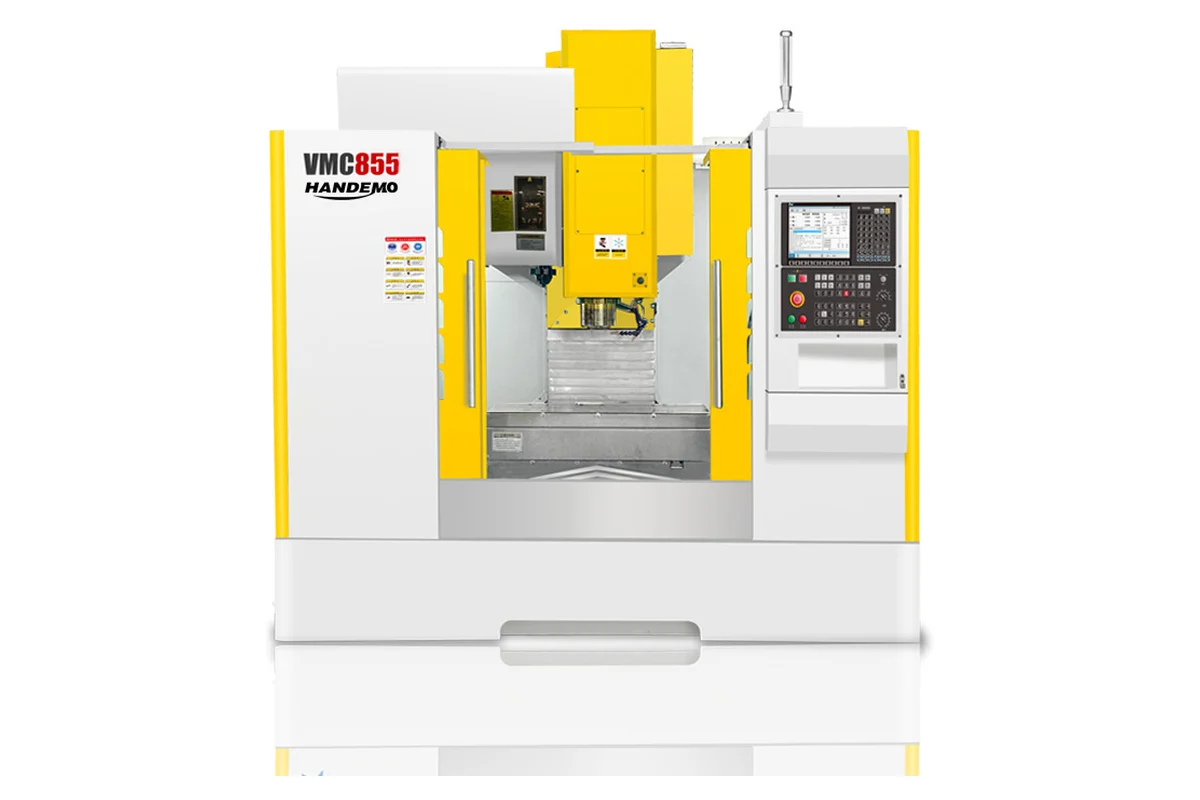
For the milled side, a VMC855 with a 1000 by 550 mm table, a 600 kg table load, 800 mm of X travel and 550 mm of Z travel, a BT40 spindle at 8000 rpm, handles the great majority of star wheels, cam plates, jaw carriers and mounting blocks. Its table is large enough to run a plate fixture with several parts at once, which is how a batch of twenty change parts should be run: one setup, one fixture, one program, and the parts come off together.
Change parts, and why they deserve their own process
A format change set is a special case because it is bought repeatedly. The first set is a project; the second, third and fourth sets are spares, and they have to match the first one without the customer sending the machine back.
The way to make that work is to treat the first set as a master and to keep the fixture. If the star wheel was cut on a fixture that locates on the bore and indexes on a pin, then the tenth star wheel is cut on the same fixture and the same program, and the only variable left is the material and the tool wear. That is a much shorter conversation than trying to re-establish the pattern from a drawing each time.
It also means the drawing has to carry the information the fixture needs. A change part drawing that gives the pocket pattern as a set of coordinates on a flat view is workable but slow. One that also gives the pitch angle, the number of stations and the datum face is much faster to program and much harder to get wrong. When we quote a change part set, we ask for the master part or a scan of it, because the drawing and the part rarely agree on the corner radii, and the corner radii are what the bottle actually touches.
Washdown, cleaning and the parts that never get clean
On a food or dairy packaging line, the machine is cleaned as often as it is run, and the parts that fail are almost never the ones that wear. They are the ones that trap product. A blind tapped hole in a product-contact block, a sharp internal corner in a valve body, a lap mark on a sealing face, a thread root that was not chased: each of these is a place where a cleaning cycle cannot reach and where something grows.
The machining consequences are specific. Blind holes get drilled deeper than the thread needs so the tap does not bottom, or they get a relief groove. Internal corners get a radius the cutter can actually produce, which is a conversation to have before the drawing is released rather than after the first part is scrapped. Sealing faces get finished with a tool that is not chipped, because a single pass with a damaged edge leaves a mark that a gasket cannot seal. Welded assemblies get the weld dressed and, where the specification calls for it, the surface treated before the final bore, because the treatment moves the material.
The same logic applies to the non-contact parts on a wet line. A star wheel in a dairy filler lives in the same washdown environment as the valve, and a pocket with a rough floor holds water and product residue. Finishing the pocket floor matters even though nothing touches it.
What to send with an enquiry
A packaging part enquiry that gets a fast, accurate quote usually contains five things. The drawing, with the datum faces marked and the number of stations or pockets stated. The material and its condition, including whether it is bar, plate, casting or a plastic grade. The quantity and whether it is a one-off or the first of a repeating set. The machine it goes on, or the mating part, because the interface is often the real specification. And the surface requirement, especially on product-contact faces where the drawing may only say "food grade".
What slows a quote down is a drawing that gives a pocket pattern without a datum, a material callout with no condition, or a change part with no master to compare against. None of those is fatal, but each one turns into a question, and a question turns into a day.
Frequently asked questions
Can a vertical machining center cut a star wheel in one setup?
Yes, if the blank arrives with the bore already finished and a fixture locates on that bore. The pockets, the outside profile and any cross holes can then be cut from one face. If the bore has to be machined from the same blank, it is a two-setup job, and that is the normal case.
What is the best material for a feed screw?
304 stainless for washdown lines and hard anodised aluminium where weight matters. For abrasive containers, a hardened stainless or a coated tool steel lasts longer, but the part has to be roughed before hardening and finished after, which changes the lead time.
How do you keep thin star wheels and guide rails from distorting?
Support the underside, keep the clamp pressure low, and take the finish pass after the part has cooled. On plastic parts, let the blank settle before the final cut. On thin stainless, leaving a small margin and finishing both faces in a second operation is usually more reliable than trying to do everything in one grip.
Do you machine change parts from a sample rather than a drawing?
Yes. For a repeat set, a master part is often more useful than the drawing, especially for pocket radii and lead-in chamfers that the drawing simplifies. We measure the master, confirm the critical interfaces with the customer, and keep the fixture so the next set matches.
What lead time should a packaging OEM plan for?
It depends on material and finishing, but the pattern is consistent: single parts in common stainless are quick, sets of change parts take longer because they are programmed and run together, and anything requiring heat treatment or surface treatment adds a step that cannot be compressed. Sending the full set in one enquiry rather than one part at a time is the single biggest saving.
Next step
If you are building a packaging line or replacing a change part set, send us the drawing, the material and the machine it fits. We will come back with a process plan and a quote, and if the part is one we have made before, we will tell you what the fixture looks like before you commit.
Email sales1@handemocnc.com or message us on WhatsApp at +86 135 6320 3038. More on the machines used for this work is on our VMC855 page, and the related guides below cover the neighbouring part families.
Related reading: CNC machining for food and beverage parts, machining thin-wall parts, machining stainless steel shafts, and machining sprockets.