Brass Spool Machining: Why It Comes Out Three-Lobed
The call came from a shop that makes hydraulic distributor blocks. They had started cutting the spools themselves instead of buying them in, and the first batch would not go into the sleeves. Not tight, not loose — oval. The spool would drop into the bore at one angle and stop dead at another, and the man doing the assembly could feel it with two fingers.
What made the call interesting was the second half of it. The shop had measured the spools on the machine, before they came out of the chuck, and the readings were good. They had also measured them on the bench, an hour later, and the readings were not. Nobody was lying and nothing was broken. The part was changing shape between the two measurements, and the reason was the chuck.
This is one of our case studies, written from the shop floor. No test sheets, no catalogue numbers. What the material does under a three-jaw chuck, why a brass part keeps a shape a steel part gives back, and what actually changed in the process.
What the Part Actually Is
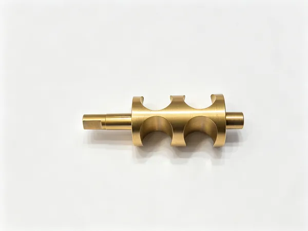
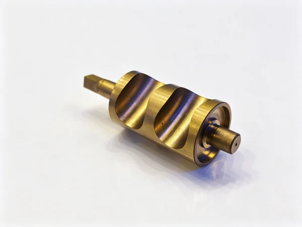
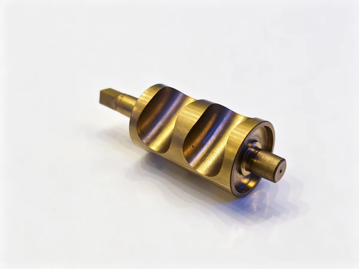
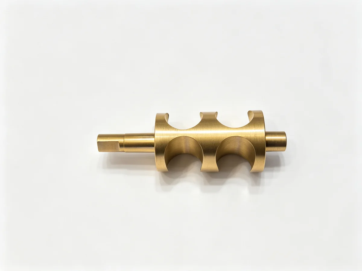
Strip away the drawing and a rotary spool is three things in a row: a shaft, a body with windows cut through it, and two ends that have to sit in bearings or bushings. Oil goes in one set of windows and comes out another, and how much goes through depends on how far the spool has rotated. That is the whole function, and it is why the shape of the body matters more than its size.
The spools in this case were a leaded brass — the free-machining family that most hydraulic and pneumatic shops know as C36000 or CuZn39Pb3, depending on which side of the world the drawing came from. The lead is there on purpose: it breaks the chip, it lubricates the tool, and it lets a shop run brass at cutting speeds that would destroy a steel tool in a minute.
The alternative material for the same part is aluminium, and it shows up whenever weight matters more than wear. Both are what our shop calls non-ferrous work, and both behave in a way that a steel part never does.
Here is the thing worth saying before anything else: the spools were not badly made. The turning was clean, the windows were milled square, the ends were faced. Every dimension on the drawing was met by the man who cut it. The part was round in the chuck and out of round on the bench, and only one of those two states matters.
Three Jaws Do Not Squeeze a Circle
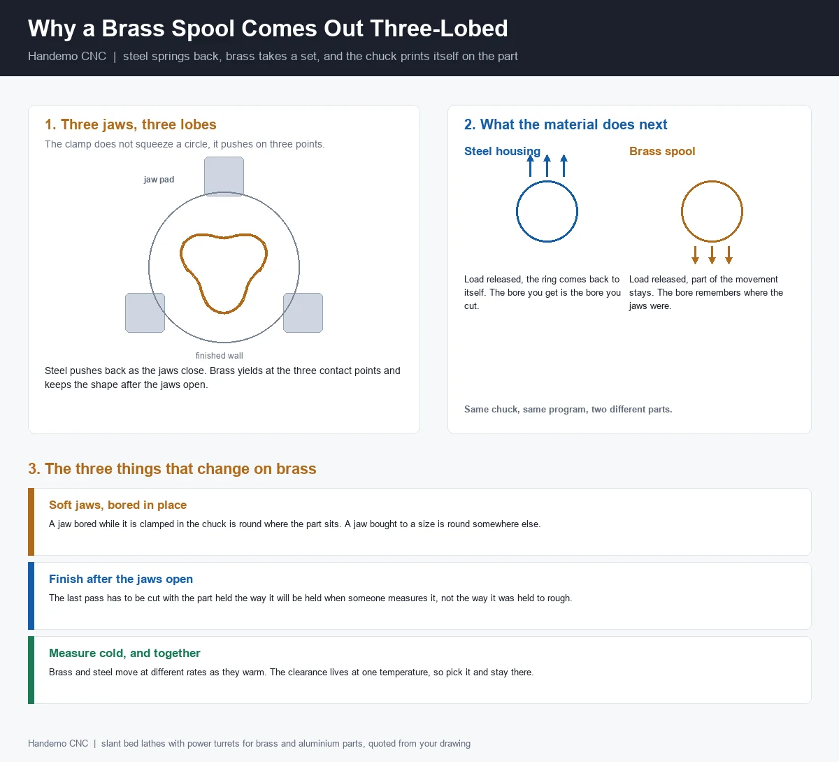
A three-jaw chuck is often described as if it closed evenly on the work. It does not. Three jaws closing on a round bar apply force at three points, and between those points the material is free to move. What happens in between is decided by the material, not by the chuck.
Close the jaws on a steel ring and the ring deflects inward at the three contact pads. The deflection is elastic — the steel is being bent, not reshaped. Cut the bore while it is bent, open the jaws, and the ring springs back towards its own shape. The bore you measured in the chuck was the bore of a deformed ring. On a steel part this is a known annoyance and shops handle it by leaving the finish for a light pass with less clamping force, or by finishing in a collet.
Close the same jaws on a brass spool and something different happens. Brass at the contact pads does not only bend — it yields. The material under each jaw pad takes a small permanent set, and the body around it follows. Open the jaws and part of the movement stays. The spool does not come back to the circle it was, because it was never a circle under load in the first place.
Steel remembers its own shape. Brass remembers the jaws.
That single sentence explains everything that went wrong in that first batch, and it also explains why the fix is not a better boring bar or a slower feed.
Why the Second Measurement Was Worse Than the First
The shop's instinct was that the part had moved after machining. In a way it had, but not the way they thought. The sequence they were running was the usual one: rough the outside and the bore, then finish the bore, then part off, then flip and finish the second end.
Two things were happening at once.
- The finishing pass was cut in a deformed body. The bore came out round relative to a spool that was being squeezed at three points. When the jaws opened, the body relaxed into a slightly different shape and carried the bore with it.
- The part was then re-chucked on a finished surface. The second operation gripped the diameter that had just been turned, and it gripped it in three places. Every clamp mark from the second chucking is a place where the part was pushed in, and the finished bore at the first end was already cut by then.
Neither of these shows up as a machine fault. The spindle is fine. The chuck is fine. The program is fine. The error is in the relationship between the clamp and the cut, and it accumulates in the part instead of in the machine.
The Fix, and Why It Costs Nothing
The fix was a change in fixtures and in the order of operations, not in the cutting data.
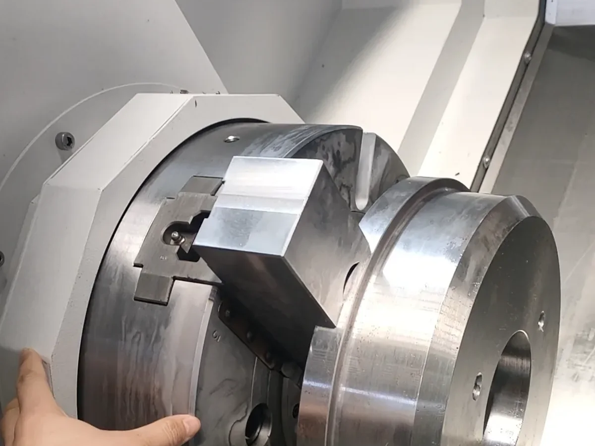
Soft jaws bored in place
A set of aluminium or mild steel soft jaws, bolted to the chuck, bored while clamped to a ring of the size the part will be held at. What that buys you is a jaw that is round where the part sits, because it was cut by the same spindle that will cut the part. A jaw bought to a nominal size is round somewhere else — in the supplier's grinder — and the difference between the two is the difference between a spool that fits and one that does not.
On a brass spool this matters more than on steel, because the jaw is not only shaping the clamp, it is limiting how much the material can yield. A jaw that contacts the part over a wide arc spreads the load across that arc. A jaw that touches on a line concentrates it, and concentrated load on brass is a permanent dent.
Rough and finish in the same grip
The roughing pass and the finishing pass now happen with the part in the same jaws, closed once, at the same pressure. The roughing cut removes most of the material; the finishing cut removes the last of it without the part being re-clamped in between. Nothing about this is clever. It simply removes the moment where the part could be squeezed into a shape and then cut.
Part off last, and part off light
The parting cut is the one operation that puts a large axial load on a small remaining section. On brass the tool has to be sharp, the feed steady, and the remaining wall thick enough that the part does not fold as the blade goes through. Where the drawing allows it, the spool is turned complete and parted off before the second end is finished, so the finished bore is never asked to survive a parting cut.
Second end on soft jaws, not on hard jaws
The second operation — the other end face, the other bearing journal — is where the first end gets damaged, because that is where a finished bore gets re-gripped. Soft jaws bored to the part's own turned size solve it: the grip is distributed, and the part sits where it sat the first time.
The Second Problem Nobody Expected: Steel Parameters on Brass
Once the spools were round, the shop found a different complaint at assembly: the spools were tight in the sleeves at one end and free at the other. That is a taper, and it came from the cutting data.
The program had been written for a steel part of a similar size and simply carried over. On brass, that program is wrong in three ways.
- The tool rubs instead of cutting. Brass wants a sharp, positive tool with a small honed edge. A tool with a land on it, run at steel feeds, presses the material away instead of shearing it. The result is a bore with a smeared surface and a shape that follows the tool pressure rather than the tool path.
- The chip wraps the part. Brass makes long, hot, stringy chips that do not break on their own. If they are not directed away from the cut, they wrap the spool, mark the finished surface, and on a thin window section they can pull the part out of shape as the chip packs.
- The part runs hot and the readings move. Brass conducts heat away from the cut faster than steel, so the part itself warms up quickly and grows. Measure it hot and it reads one way; let it sit and it reads another. On a part where the fit against a steel sleeve is the whole point, that difference is enough to send a good batch back to the bench.
The correction is not exotic. Sharp inserts for non-ferrous work, a feed that keeps the tool cutting rather than pressing, coolant aimed at the chip rather than at the part, and a finishing pass that leaves the material cool enough to measure honestly.
Why a Brass Spool and a Steel Sleeve Do Not Agree at the Bench
Brass grows more than steel for the same rise in temperature. It is not a large difference, but the fit between a brass spool and a steel sleeve is decided in the last part of the clearance, so a small difference is the whole conversation.
What that means in practice is that the clearance has to be chosen at one temperature and checked at that temperature. Two rules came out of this case and both are now in our process notes.
- Measure after the part has settled, not when it comes off the machine. A spool that is warm from a finishing pass is not the spool the assembly will see. Let it cool on a bench, in the same room, and measure it there.
- Measure the pair together. The spool and the sleeve it will run in should be measured in the same room, at the same time, with the same instrument. A spool measured in the inspection room and a sleeve measured at the assembly bench are two numbers taken in two different worlds.
This is also the reason a brass part is a poor candidate for the "cut it to the middle of the band and ship it" approach. The middle of the band is only meaningful if both parts are read at one temperature.
The Windows Are Why This Part Is Not Just a Turning Job
A spool body with metering windows is not a turned part with a couple of milled features added afterwards. The windows and the bore have to agree, because the amount of oil that passes is set by the edge of the window against the edge of the port in the sleeve.
Two routes work, and which one is right depends on the batch.
- Turn, then mill on a second machine. The spool is turned complete, then moved to a machining center where the windows are milled with the part held on a fixture. Correct, but it is a second setup, a second clamp on a finished bore, and a second chance for the part to be pushed out of shape.
- Turn and mill in one clamp. A lathe with a power turret and driven tools cuts the windows without the part leaving the spindle. The window edges are then cut relative to a bore that has not been re-gripped, which is exactly the relationship the function needs.
For the batch in this case — a family of spools in three sizes, running in the low hundreds — the second route was the cheaper one, and not because the machine is faster. It was cheaper because it removed a clamp from a brass part that had already shown what a clamp can do to it.
The Machines We Would Put This On
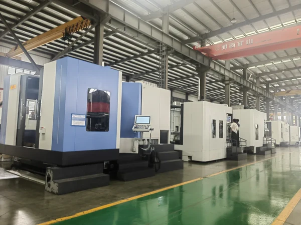
Machine choice for non-ferrous spool work is decided by the bar and the turret, not by the spindle speed. The four machines below are the ones we quote most often for this family of part, and each one is here for a different reason.
| Machine | Working envelope | Why this one for brass spools |
|---|---|---|
| TCK50 | 360 mm cutting diameter, 65 mm spindle bore, 50 mm bar capacity, 8-station turret | The plain answer for bar-fed brass. Fifty millimetres of bar covers most spool bodies without sawing, and the 8-station turret leaves room for the turning tools plus a groove tool. |
| TCK56D-500 | 300 mm cutting diameter, 400 mm cutting length, 12-station power turret | The first step up when the windows have to come off the same clamp. Driven tools on a 12-station turret put the milling on the lathe, and the part never sees a second chuck. |
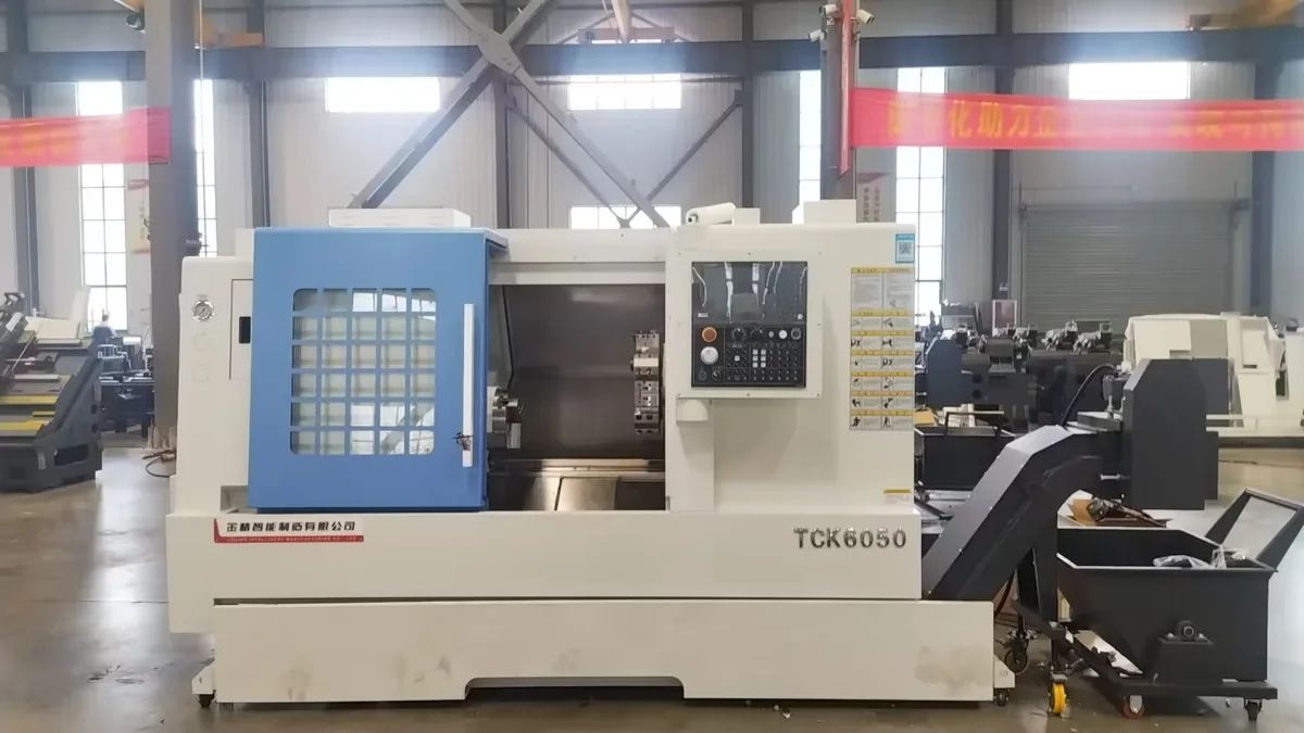
| TCK6050 | 500 mm cutting diameter, 550 mm cutting length, 65 mm bore, 12-station servo turret | The general-purpose choice for a mixed order book. Long enough for a spool with a shaft on one end, and heavy enough that a brass body does not ring when the windows are milled. |
| TCK600D | 430 mm cutting diameter, 550 mm cutting length, 70 mm bar capacity, BMT65 power turret, 10-inch chuck | For the larger spools and for work that needs a bigger chuck than a bar machine gives. BMT65 driven tools take a heavier milling cut in brass without the turret complaining. |
None of these is a "brass machine". They are lathes that happen to have the bore, the bar capacity and the turret the part needs, which is the only honest way to buy a machine for this work. If the spool is small and the volume is high, the bar machine wins. If the windows matter, the power turret wins. If the body is large and the batch is mixed, the bigger chuck wins.
Aluminium Is Not Brass Either
The same shop asked, reasonably, whether the soft jaws would also fix the aluminium end caps they make for the same block. It is a fair question and the answer is that aluminium has its own version of the problem, with one extra ingredient.
Aluminium yields even more readily than brass — a jaw that contacts on a line will mark it, and a bore cut in a squeezed aluminium body will be out of round in the same three places. But aluminium also cuts hot and sticks. A tool that is not sharp enough will build up material on its edge, and a built-up edge is a small, uneven cutting tool that changes size while it works. The result is a bore that is round but has a shape that follows the build-up rather than the program.
So the rules overlap but they are not the same list:
- Brass wants a sharp edge, a feed that cuts rather than presses, and a chip that is thrown clear instead of wrapping the part.
- Aluminium wants a sharper edge still, a cutting fluid that keeps the tool clean, and enough speed that the tool cuts instead of rubbing — with a clamp light enough that a 4 mm wall is not asked to hold more than it can.
- Both want the same thing from the chuck: a grip that is distributed, closed once, and set to the pressure the part can take.
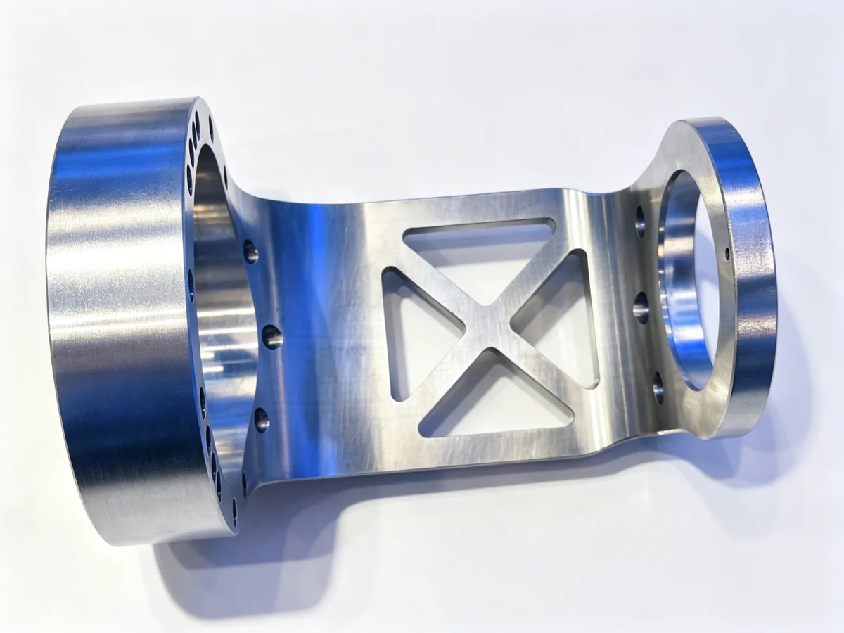
The aluminium frame part below is the same argument in a different shape. Two bores, both of which have to line up, and a lightening window pattern that takes most of the material out from between them. Grip that on the outside diameter in hard jaws and the two bores will not agree, because the frame between them was squeezed while it was being cut.
The Cost That Never Appears on the Quote
The first batch of spools was not scrap. That is what made it expensive. Every spool met its drawing, every spool was accepted by the inspection bench, and the loss only appeared at assembly, one part at a time, as a fitter trying spools into sleeves and putting the tight ones aside.
Add up what that costs and none of it is in the cutting time:
- The fitter's hours spent trying parts that should have been interchangeable.
- The bench work of re-polishing or re-cutting the ones that were only slightly out.
- The scrap on the ones that were not recoverable.
- The delivery date that moved, and the conversation with the customer that followed it.
Against that, a set of soft jaws and a re-ordered process cost a shift. This is the pattern we see over and over on non-ferrous work: the money is not lost in the cut, it is lost at the point where two parts made in two different grips are asked to fit each other.
The scrap you can see is cheap. The fit you cannot explain is what costs.
Clamping Rules That Came Out of This Job
Four rules, all cheap, all now standard on non-ferrous work in our shop.
- Never finish a brass bore in hard jaws. Soft jaws, bored in place, at the size the part will be held at. If the part is small enough for a collet, use the collet — a collet closes on many points or on a full circumference, and it does not print three lobes.
- Close the chuck once. Rough and finish in the same grip wherever the geometry allows. Every additional clamp on a finished surface is a chance to move it.
- Keep the clamp pressure down. Brass does not need the pressure a steel blank needs. Enough to hold the part against the cut, and no more, because everything above that is being stored in the material.
- Support the thin section. A spool body with windows cut through it is not a tube any more, it is a cage. Where the wall between windows is thin, a plug or a low-pressure support in the bore during the milling pass keeps the cage from closing in.
The Sequence We Run Now
For a brass spool that has to come off one machine with its windows cut:
- Bar fed through the spindle, or a sawn billet chucked in soft jaws where the bar is too large.
- Face the first end, rough the outside and the bore, in one grip.
- Finish the outside, the bore and the first journal without opening the jaws.
- Driven tools cut the windows and any cross holes, still in the same grip.
- Part off, if the machine is bar fed, or move to the second operation on soft jaws bored to the turned size.
- Second end: face, journal, and any feature that could not be reached from the first side.
- Deburr the window edges by hand or with a brush tool, then let the part settle before it is measured.
- Measure the spool against its sleeve, in the same room, after both have cooled.
Two of those steps are not cutting at all. They are the ones that decide whether the batch goes together at assembly, which is a sentence that applies to almost every non-ferrous part we quote.
What We Need to Quote It
Send the drawing and these five things, and the quote comes back with a machine and a sequence rather than a price per piece:
- The material and its temper, not just the name. Leaded brass, tellurium copper and a plain aluminium bar are three different jobs.
- Whether the windows or cross holes exist, and whether they have to come off the same clamp as the bore.
- The bar size or the billet size, because it decides whether the part is bar fed or chucked.
- The sleeve or mating part it runs in, with the fit drawn on it. That is where the argument will be if anything goes wrong.
- Batch size and whether it repeats. A one-off spool can be made on a lathe and a mill; a repeating family wants one clamp.
Related Reading
If the part in your hand is closer to a bushing than a spool, our guide to bushings, sleeves and ring parts covers the same clamping problem from the other direction. The expansion sleeve case is about a thin brass sleeve that had to be turned without a grinder. For a steel part that behaves the way a spool does not, the thin-wall motor plate case shows what happens when a part is gripped on a surface it has already finished.
If the choice is between a bar machine and a chuck machine, our lathe selection guide sets out what swing, bore and chuck actually mean. And if the part is a bronze bushing pressed into a steel housing, the piston guide sleeve case is the closest thing on the site to this job.
Frequently Asked Questions
Why does a brass part go oval but a steel part does not?
Steel deflects under the jaws and springs back when they open, so the shape it had before clamping is the shape it returns to. Brass yields at the three contact points and keeps part of that movement, so the shape after clamping is not the shape before it. Same chuck, same pressure, two different outcomes — the material decides, not the machine.
Can a collet replace soft jaws for this?
For bar work up to the collet's range, yes, and it is the better answer because a collet closes around the whole circumference or on many segments. Above that range, or for a part with an interrupted outside diameter, soft jaws bored in place are the practical choice.
Do the jaws have to be bored on the machine that runs the job?
They have to be bored by the spindle that will hold them, at the diameter the part will be held at. In practice that means boring them in place on the machine, with the chuck pressure set to what the job will use. Jaws bored on another machine, or bored at a different pressure, are round in the wrong place.
Is leaded brass still available where we are?
It depends on the market. Leaded free-machining brass is restricted in some places and unrestricted in others, and the substitute grades machine differently — usually with a shorter chip and a different tool edge. Tell us which grade you can buy and the process is planned around that, rather than around the drawing's original material.
How do you hold the windows without the body closing in?
A light support in the bore during the milling pass, plus a milling strategy that does not cut the two opposite windows in the same revolution of the part. If the wall between windows is very thin, the order of the windows matters as much as the fixture.
Can the same machine do the brass spools and the steel sleeves?
Yes, and many shops do exactly that. What changes between the two is the clamping, the tool edge, the chip control and the temperature at which the part is measured — not the machine. A lathe set up for brass will run a steel sleeve, but the jaws and the program have to be treated as two separate jobs.
What if the spool is already made and only the fit is wrong?
That is a recovery question and it depends on where the error is. If the body is oval, the bore can sometimes be re-cut with the part on soft jaws — but only if there is material left to cut. If the taper is in the journal, the journal can be re-turned. Send us the readings from both ends and we will tell you whether it is recoverable or whether the batch is scrap.
Talk to Us About Your Spool
If you have a brass or aluminium part that measures well in the chuck and badly on the bench, send the drawing and tell us what the assembly does when it goes together. That description usually finds the problem faster than the drawing does. You can reach us at sales1@handemocnc.com or on WhatsApp at +86 135 6320 3038, or upload the drawing through the quote page and we will come back with the clamping and the machine we would use.