CNC Machining a Hydraulic Piston Guide Sleeve
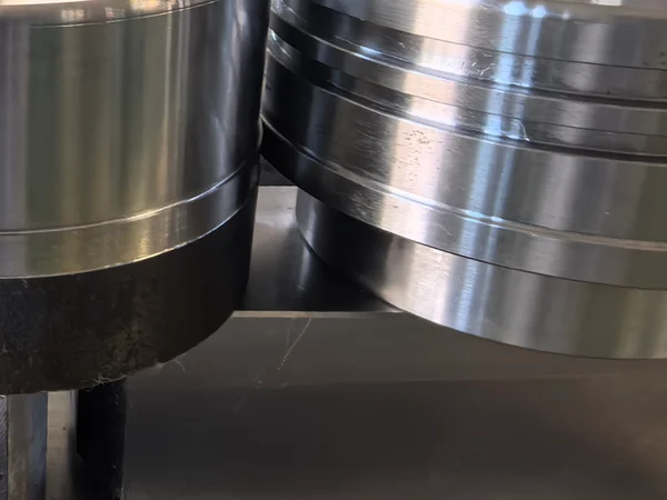
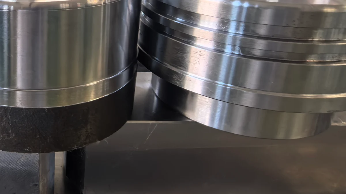
Some parts arrive as a drawing with a long tolerance stack and no notes. Others arrive as a photograph, two sleeves side by side, one dull and one bright, with a single line underneath: can you do the one on the right, at this price? That second kind of enquiry is where a guide sleeve job usually starts, and it is where the whole quotation is decided, long before anyone prices a machine hour.
A piston guide sleeve looks almost too simple to machine. It is a ring. It has a bore, an outside diameter, two ends and a shoulder. There is nothing on it that a lathe cannot reach. The difficulty is entirely in the finish, the roundness, and the fact that the wall is thin enough to move when you clamp it — which is why the same drawing can run without a single rejection at one shop and never settle down at another.
What the Guide Sleeve Actually Does
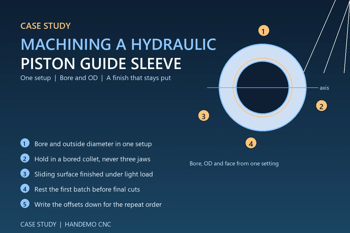
The sleeve guides a piston or a rod. It keeps the moving part on its axis and it carries the side load so the cylinder wall does not have to. That job description sets the priorities on the drawing: the bore has to be straight and round along its whole length, the outside diameter has to be concentric with it, and the sliding surface has to be smooth enough that the seal or the piston does not scuff it in the first hundred cycles.
In the sleeves we see most often, the requirements read like this:
- Bore roundness and straightness held over the full length, not just at the ends
- Outside diameter concentric to the bore, usually called out as total runout
- A sliding surface finish that suits a reciprocating seal, produced without polishing marks that cross the bore axis
- Length and shoulder faces square to the axis
Nothing on that list is exotic. What makes it a real job is meeting all four at once, on a thin ring, in production, batch after batch.
Finish Is Decided Before the First Cut
Shops that struggle with a sleeve finish usually blame the insert. Usually it is not the insert. A reciprocating seal surface is sensitive to three things, in this order: the stability of the setup, the condition of the edge that was on the part last, and the way the finishing pass was approached.
If the sleeve is held in a three-jaw chuck on its outside diameter, the jaws push it into a three-lobed shape before the tool touches it. The bore gets cut round in the chuck and springs back to a lobe when the jaws release. The surface looks fine on the machine and the part does not fit the gauge. The photograph that started this order — the dull sleeve next to the bright one — was very often a clamping result rather than a tool wear problem.
Blanks: Bar, Tube or Casting
Most guide sleeves in this size range start from either a tube blank or a solid bar. Tube is cheaper on material and cheaper on lathe time, because there is no big core to remove, but tube arrives with its own internal stress and with a wall thickness that may not be concentric. Bar costs more to remove but gives a homogeneous, predictable blank. For a long run of a thin sleeve the tube route normally wins on cost — provided the first operation removes wall thickness evenly all round, which is exactly what a short bar does not let you check.
For sleeves cut from a casting or a forged blank, the first operation should be a roughing pass that removes skin and metal on both bore and outside diameter, followed by a rest before finishing. That rest lets the material move once, on the machine, rather than after the part has been gauged and packed. On any sleeve where the wall is thin relative to its diameter we recommend finishing a first batch and letting it sit overnight before the last light cuts. It costs one day on the schedule and it removes a whole class of complaints.
Why One Setup Usually Beats Two
Concentricity between the bore and the outside diameter is the one feature a guide sleeve cannot negotiate on. Every time you re-chuck the part, part of that concentricity goes back into the hands of the jaws and the operator. Cutting the bore and the outside diameter from the same setting removes the question entirely.
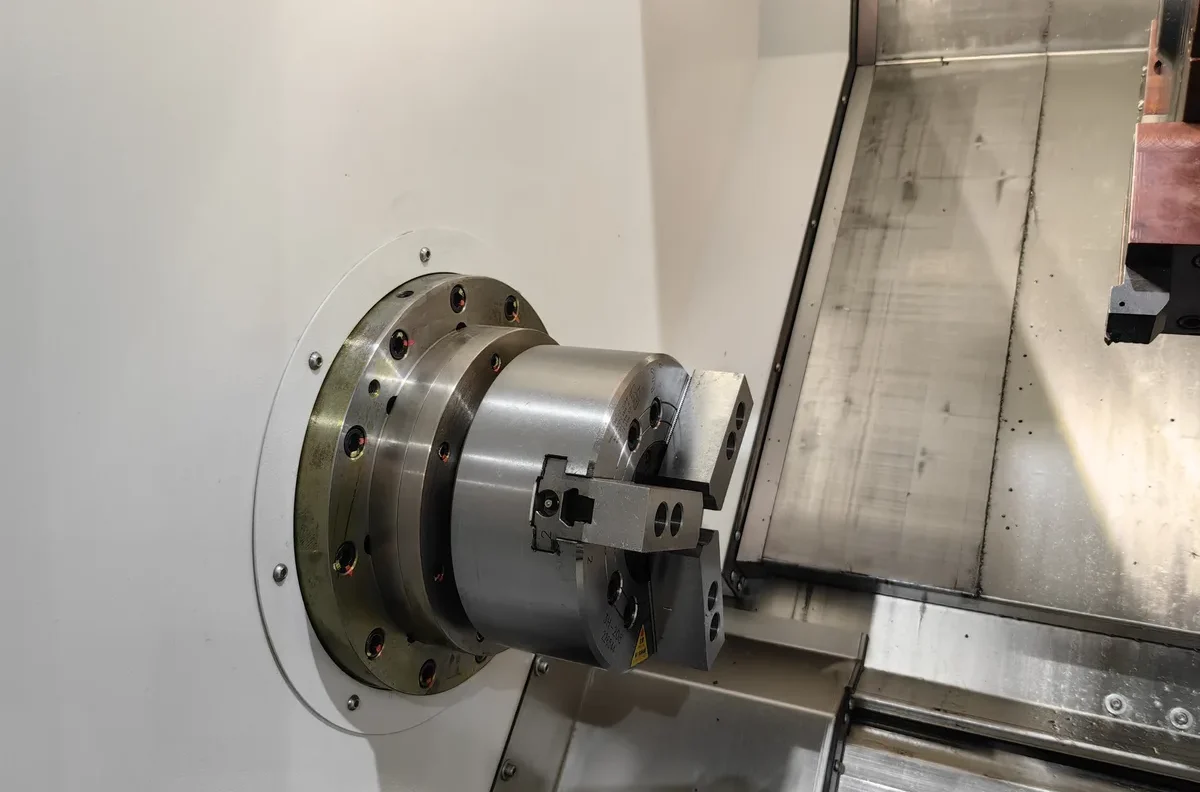
That is the practical argument for a machine that puts more operations on one part in one clamping. Turning the outside diameter, boring, facing the shoulder and, if the drawing calls for them, drilling and tapping the flange holes, all from a single setup, is what a mill-turn or Y-axis turning centre is built for. On the TCK6050 CNC slant bed lathe the slant bed keeps chips falling clear of the cut and the operator can watch the bore while it is cutting, which matters more than it sounds when the whole job is surface quality.
Where the annual volume is high and the part has features on both ends — a stepped outside diameter at one end, a counterbore at the other — a dual-spindle machine removes the second operation completely. The part transfers from the main spindle to the sub-spindle and the back end is finished without ever leaving the machine. On a sleeve that transfer is worth more than the cycle time saving, because it also removes the second clamping event and therefore one more chance for the ring to distort. A dual-spindle mill-turn machine such as the TCK6050SY is the configuration we would quote for that family of part.
Holding a Thin Sleeve Without Distorting It
Once the setup count is down to one, the remaining risk is clamping load. Three practical options, in the order we usually try them:
- A soft, bored-to-size collet or a split bushing with a wide contact band. The load is spread around the circumference instead of concentrated at three jaws, and the sleeve is supported all the way round.
- Face clamping plus light outside diameter support, so the axial load seats the part on the shoulder face and the boring bar cuts with the ring backed up.
- Turning between centres, or from a stub mandrel, for sleeves long enough that the overhang itself starts to deflect. On a long, thin sleeve that deflection is the largest single source of taper in the bore, and no insert geometry will fix it.
Keep the finishing cut light and let the part find its own shape under a small load. On a thin ring that is not a compromise, it is the honest way to cut it.
Keeping a Run Consistent
Once a sleeve is running well the job stops being about geometry. It becomes about repeatability across a shift, across a week, and across a second batch three months later. Three things carry that:
A gauge-led loop. One dedicated gauge for the bore on the shop floor, checked against the master at the start of each shift, with the offset corrected from the gauge rather than from the operator's impression of the last part. On a thin sleeve the gauge itself, if it is a plug that loads the ring, will read differently from the measuring method used in the inspection room. Agree the method with the customer before the first batch, not after the first argument.
Temperature discipline. Thin rings follow the shop temperature within minutes. A bore that reads at the end of the afternoon and one that reads first thing in the morning are not the same part. Let the part and the gauge come to the same temperature before the final decision, and keep the gauge away from the door.
A written offset log. The person who sets the sleeve job in October is not always the person who set it in May. A short log of the insert used, the offsets that settled the job in, and the clamping method costs nothing to keep, and it is the difference between a second batch and a second development project.
What the Order Looked Like
The sleeves in these photographs came to us from a shop working in general machinery components — the hydraulic and pneumatic side of it, pistons and guides. They had been turning the part in two operations, and the finish was inconsistent enough that the sliding surface was being touched up by hand before assembly. The comparison photograph they sent showed one of our test parts next to theirs.
The change that moved the job was not a new insert or a higher cutting speed. It was holding the sleeve in a bored collet with a full contact band, and finishing the bore and the outside diameter from one setting, with a light finishing pass and a rest before the last cut. Their measured readings on the sliding surface settled into a tighter band on our machine than on their existing process, and the hand touch-up step came out of the routing. The batch was quoted, run, and the same clamping method was written down for the repeat order.
That is a fairly ordinary result, and that is the point. Guide sleeves are rarely lost on machine capability. They are lost on clamping, on setup count, and on whether anyone wrote down what worked.
FAQ
Can you machine a guide sleeve from tube instead of bar?
Yes, and for volume work it is usually the cheaper route. The first operation has to remove wall thickness evenly so the tube's own eccentricity is cut away rather than pushed from one side of the part to the other. We normally rough both bore and outside diameter, rest the parts, then finish.
Do we need a mill-turn machine, or will a standard lathe do?
If the sleeve carries only turning features, a slant bed lathe with the right workholding will run it. If it has cross-drilled holes, a flange bolt pattern, or features on both ends, a Y-axis or mill-turn machine removes the second operation, and with it the second clamping.
How do you stop the bore going out of round?
By not using three-point contact on a thin wall. A bored collet, a split bushing or a mandrel spreads the clamping load around the circumference. The second step is a light finishing cut, so the tool is not pushing the wall ahead of itself.
What materials do you usually see for these sleeves?
Free-cutting and medium-carbon steels, case-hardening steels where the sliding surface will be hardened, and bronze or cast iron for guide bushes. The material changes the insert and the cutting data, not the setup logic.
Can you quote from a photograph before we send the drawing?
Send the photograph. It tells us the shape, the likely wall thickness and the finish target, and it usually tells us something about what is going wrong on the current process. The firm quotation needs the drawing and the annual quantity, but the first answer does not.
Send Us the Part You Are Struggling With
If a sleeve is running but not settling — a finish that drifts, a bore that will not hold, a hand touch-up step you would like to take out of the routing — send the drawing and a photograph of the part as it comes off your machine. Our team will come back with a machine recommendation and a process note, not just a price.
Contact Handemo CNC | Email: sales1@handemocnc.com | WhatsApp: +86 135 6320 3038
Related reading: CNC Machining Guide for Hydraulic Valve Bodies | CNC Machines for Valve & Hydraulic Parts | More Handemo case studies