CNC Machining Pump Parts: Casings, Impellers and Bodies
Nobody walks past a pump and admires it. It sits behind a guard, humming, until the day it leaks, cavitates or eats its own wear rings. Then it becomes the most important machine in the plant. Which is a shame, because by the time a pump or a valve body is being machined, almost everything that decides whether it lasts has already been fixed: how the casing bore lines up with the flange faces, how true the impeller sits on its shaft, whether the seal face and the bearing bore were cut from the same location.
Pump and fluid-power parts are a distinctive family of work. They are open, thin-walled and full of intersecting bores, and they leak if the bore and the sealing face do not agree. This is not the same as machining a gearbox housing, where the walls are thick and the features are mostly parallel. It is closer to sheet-metal thinking in a cast part.
This guide is part of our CNC machining application guides series. It looks at what the family contains, how the shapes behave under a clamp, and which machines actually suit them.
What the family actually contains
“Pump parts” is a loose label that hides five quite different jobs:
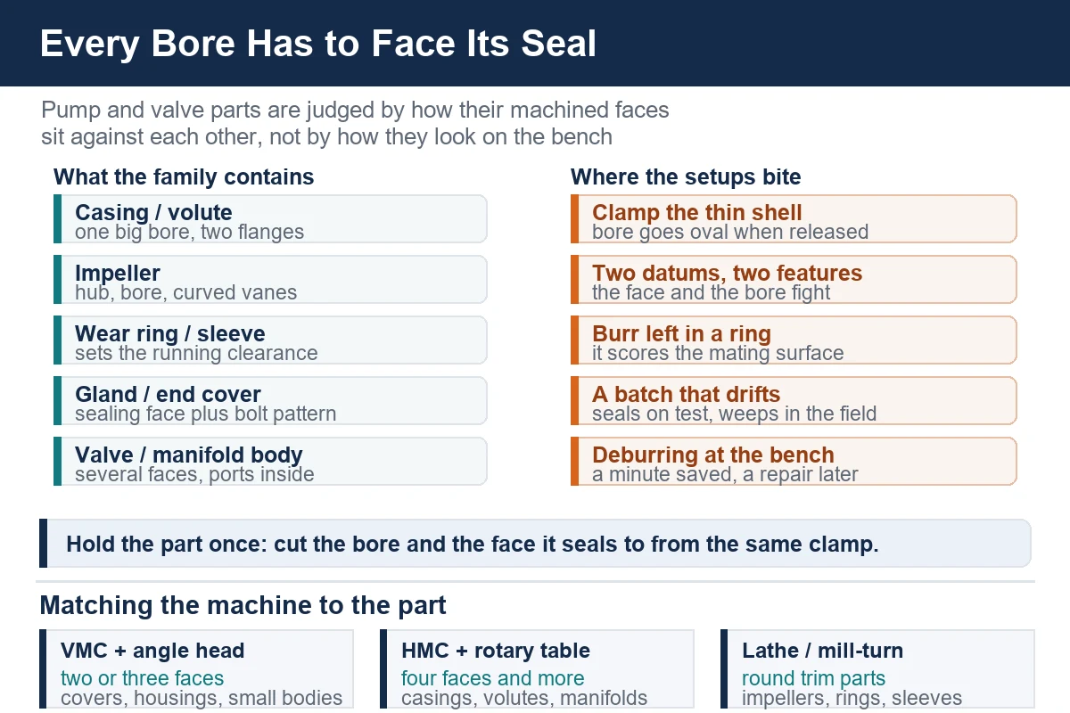
- casings and volutes: a cast shell with a large internal bore, a suction and a discharge flange, and a foot or a mounting pad
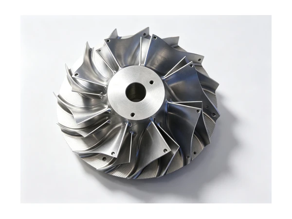
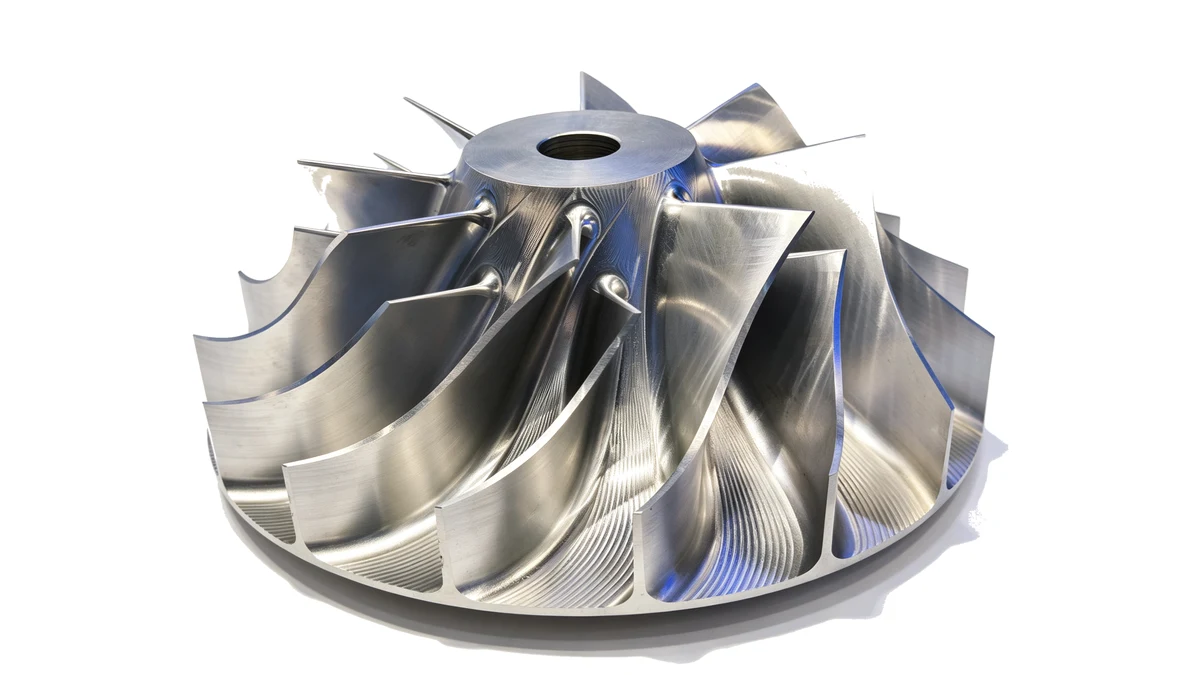
- impellers: a hub, a bore, and vanes that are open, semi-open or enclosed
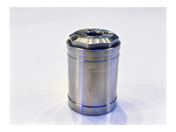
- wear rings, bushes and sleeves: simple round parts that live inside the casing and set the running clearance
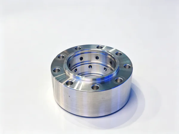
- glands, end covers and seal housings: a face that has to seal, a bore that has to align, and often a set of small holes on a pattern
- valve and manifold bodies: a block or a ball with several internal ports and two to six machined faces
The common thread is that almost every part in the list is a container of some kind. The machined surfaces are a set of faces and bores that have to hold a seal, carry a bearing, or guide a moving element. Once you see the parts that way, the machining plan writes itself.
Materials you will meet
Grey iron and ductile iron
The default for water, oil and process pumps. It casts to a near-net shell, machines easily and damps vibration. The casting skin is hard and abrasive, so the first pass takes scale and the second takes iron. Iron is also brittle in thin sections: a volute wall is not a place to apply a heavy clamp.
Stainless, duplex and super duplex
Where the fluid is corrosive, the casing and the trim go stainless. These alloys work-harden, so a tool that rubs instead of cutting will glaze the surface and blunt the next insert. Duplex grades add a second problem: the heat of machining affects the balance between the two phases, so the cutting strategy matters as much as the tool grade. A rigid setup that keeps the tool engaged is the practical answer.
Bronze, gunmetal and aluminium
Bronze appears in seawater and legacy pumps, and in the wear rings and bushes. It cuts freely but galls and picks up if the tool dwells. Aluminium casings turn up in air and light-duty applications and behave like any other aluminium: light cuts, sharp tools, and clamps that do not mark the surface.
Machining the casing
The volute is a fixture problem before it is a cutting problem
A pump casing is judged by two things: the main bore that carries the shaft and the impeller, and the two flanges that bolt into the pipework. Get those three features out of agreement and the pump will run, then vibrate, then fail. The practical route is to hold the casting on its own machined mounting foot or pad, and take the bearing bore, the seal face and the flange faces from that single location.
The catch is that a casing is a thin shell. Clamp it on the outside of the volute and the bore comes out oval; release the clamp and the out-of-roundness shows up in the running clearance. The usual answer is to clamp on the foot, support on machined pads prepared in an earlier cheap operation, and keep clamp force low and even.
Facing the flanges and drilling the bolt circle
Suction and discharge flanges are face-and-bolt-circle work. The face has to sit square to the bore, and the bolt circle has to be concentric with the face so the gasket compresses evenly. On a machine where the part can be indexed, both flanges and the main bore can be cut without disturbing the casting. On a vertical machine, a right-angle head and a tombstone fixture get to the same result with more setup discipline.
The foot and the datum
Casing feet are usually machined early and lightly, because they become the reference for everything after them. It is tempting to leave the foot rough and chase the bore; the shops that run these parts well do the opposite.
Machining the impeller
The bore and the hub
The impeller bore carries the shaft, and the hub face sets the axial position. If the two are not cut in the same chucking, the impeller runs out on the shaft and the pump vibrates at running speed. On a lathe with a bar feeder or a chuck and a steady support, the bore, the hub face and the outside diameter are a single-setting job. Where the impeller also carries a keyway or a cross-drilled hole for a shaft pin, a Y-axis mill-turn centre keeps the drilling and the turning on one datum.
The vanes
Open impellers are often trimmed and faced on the lathe. Semi-open and enclosed impellers with curved or twisted vanes are the case for a machine with a rotary or tilting axis, where the tool can follow the blade instead of stopping short of it. Mould and die shops already know this kind of toolpath from cavity work.
Balance is a machining decision
An impeller that is geometrically perfect can still be out of balance if one side of the shroud is cut deeper than the other. The fix is not a balancing machine at the end of the line; it is a process that removes material from the two sides in the same way, on the same setup, part after part.
Wear rings, sleeves and bushes
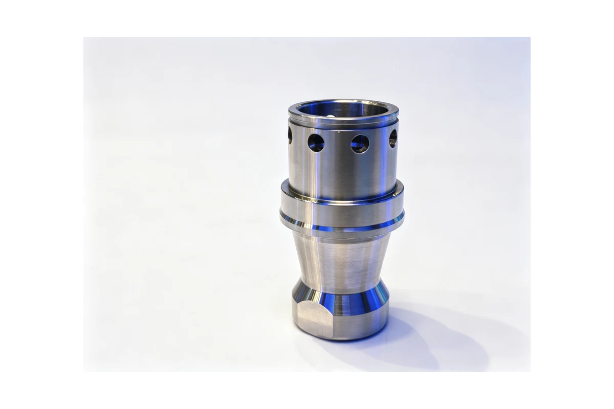
These look like easy parts, and in isolation they are. Their whole job is to set a running clearance, which means the outside diameter and the bore have to share an axis and the shoulders have to sit square. Turned in one setting, they behave. Turned in two, with the part flipped and rechucked on a raw surface, they become the reason a pump eats itself in six months.
The other quiet issue is burr. A raised edge on a wear ring bore scores the mating surface on assembly. Deburring inside the cycle costs seconds; finding the score on a customer's test bench costs the order.
Valve and manifold bodies
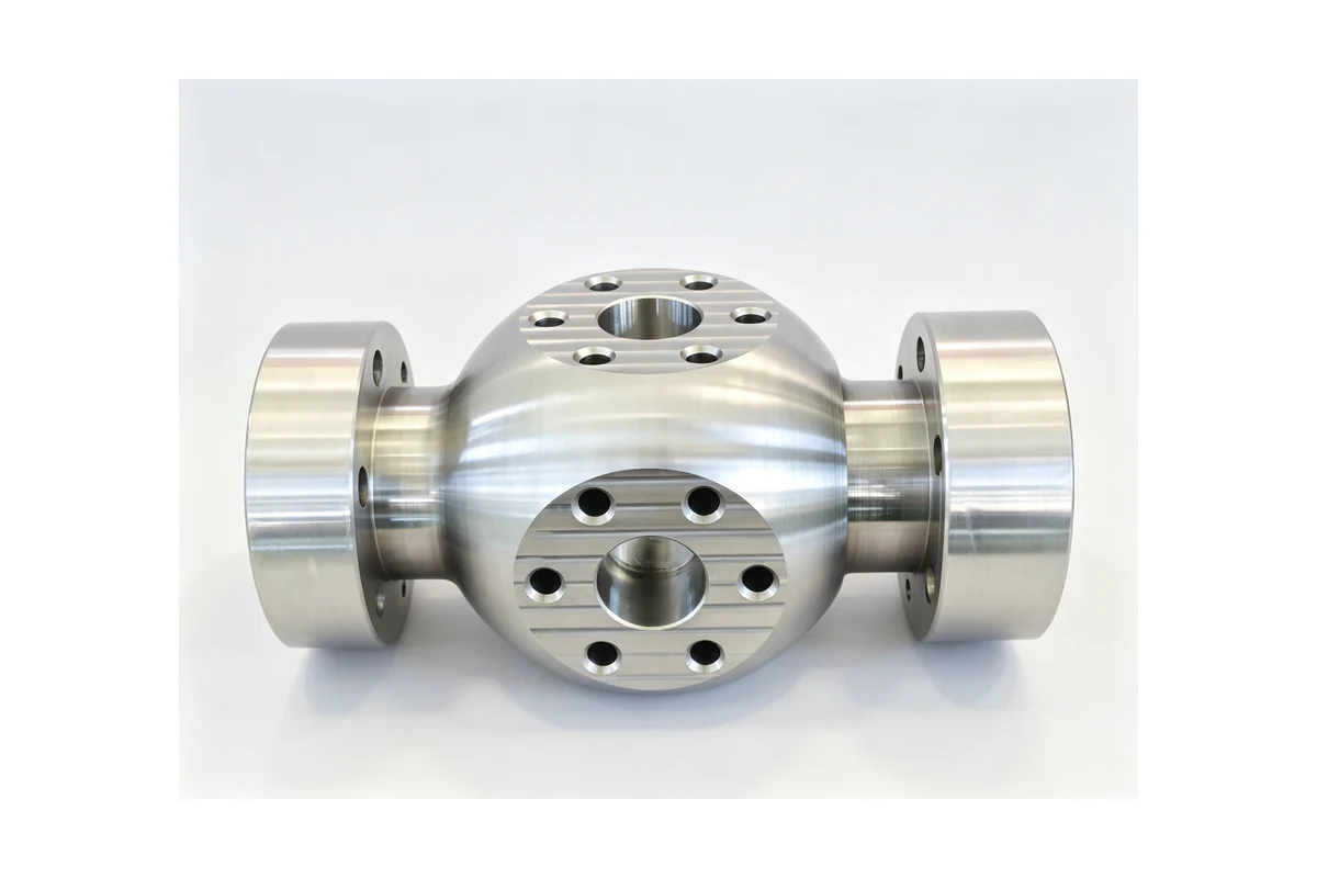
A manifold or valve body is a box with a cavity hidden inside it. Every machined face is a sealing surface, and every port pattern has to land on the internal passage. If one face is cut from a different datum to its neighbour, the gasket loads unevenly and the joint weeps.
These parts reward a horizontal machine with a rotary table. Clamp the body once, index to each face in turn, and cut the port and the face on the same setting. Vertical machines handle the family comfortably when the part has two or three faces, especially with a tombstone that lets two or three parts share the cycle. The detail that decides the result is the same one that decides a casing: the datum is picked once and everything references it.
Matching the machine to the part
There is no single answer, but the family does fall into recognisable bands.
Vertical machining centres
For two- or three-face work, a vertical machine with a right-angle head is the economical route. A VMC1160 takes pump end covers, seal housings, smaller valve bodies and casing covers comfortably, and a tombstone fixture keeps utilisation up when the parts are small. It is the sensible entry machine for a shop moving into fluid-handling work.
Horizontal machining centres
Where a casing or a body has four or more machined faces, the horizontal pays for itself. The part stays clamped on one datum while the table indexes, which is the difference between a bore and a face agreeing and a bore and a face fighting. The HMC630-DT covers small and medium casings; larger volutes and multi-port bodies with long bores suit the deep-hole and T-type machines in the same range.
Lathes and mill-turn centres
Impellers, shafts, sleeves and wear rings are turning work first. A TCK6050 handles the smaller hubs, rings and bushes, and where the part needs turning plus cross-drilling, a keyway or a port, a Y-axis mill-turn centre such as the TCK2300B finishes it in one chucking instead of two machines. For complex impeller vanes and larger trim parts, a machine with an added rotary or tilting axis follows the blade instead of stopping at it.
Keeping a batch together
Fluid parts leak as a population, not as individuals. A pump that seals on the test stand and weeps in the field is almost always a batch that drifted: the clamp force crept up, an insert was changed a little late, the casting moved between suppliers. The controls that keep a family like this consistent are unglamorous:
- machine the datum pad in its own short operation, and check it is clean and flat before the main setup
- hold clamp force constant from part to part, ideally with a torque-controlled or hydraulic clamp rather than an operator's feel
- change inserts on a count, and note the count with the batch
- gauge against the fixture, and trend the readings, rather than inspecting a finished part on a bench
These habits are also what make a pump family profitable. Once the setup is stable, the cycle is predictable and the rework disappears.
Where automation earns its place
Pump and valve parts run in stable families with long cycles, which makes them a natural fit for robotic machine tending. The robot loads to the same pads, in the same order, with the same force, every cycle — and clamp consistency is the one variable an operator genuinely cannot control by hand. It also lets one person run several machines, which changes the arithmetic on a multi-machine cell.
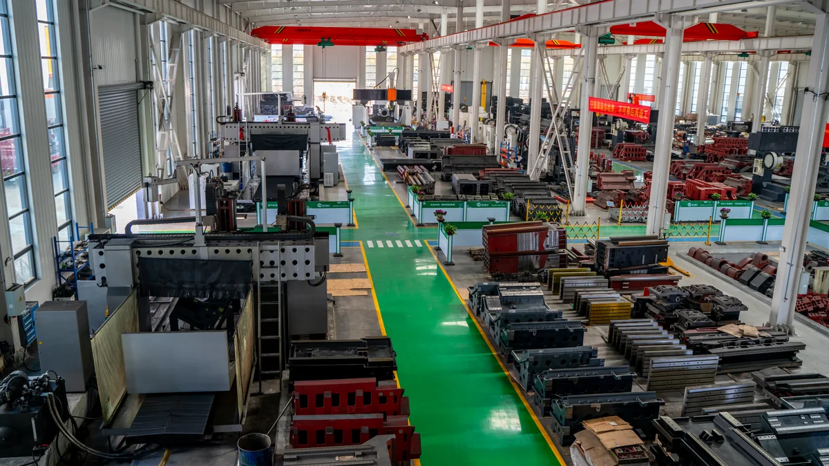
Handemo CNC has been building machine tools since 2008, with a 220,000 square metre plant, more than 660 employees, and machines running in over 150 countries. Much of that base is job shops and manufacturers making exactly this class of part.
Frequently asked questions
Can a pump casing bore and its flange faces be machined in one setup?
Usually yes, and it is the best answer when the volume justifies it. A horizontal machine with a rotary table holds the casting on its foot, cuts the bearing bore and the seal face, then indexes to the suction and discharge flanges. The alternative is a vertical machine with a right-angle head and a well-made fixture, with the trade-off being more setups and more chances for the datum to slip.
Do you machine impellers, or only the casings?
Both. Impeller bores, hub faces and outside diameters are turning work and run on our lathes. Open and semi-open impellers with curved or twisted vanes need a machine that can follow the blade, which is where a mill-turn or multi-axis machine takes over.
How do you stop a thin-walled casing from distorting?
Two things. First, clamp on the part's own mounting foot or a machined pad rather than on the shell, and keep the force low and even. Second, prepare those pads in a separate short operation so the main setup has something true to sit on.
Which stainless grade should a casing be?
It follows the fluid, not the machine. Water and light chemicals usually sit in a standard austenitic grade; chlorides and aggressive media push towards duplex or super duplex. Tell us the fluid and the temperature and we will machine to the drawing the application calls for.
What is the difference between a wear ring and a sleeve?
A wear ring is fitted to the casing or the impeller and sets the running clearance; a sleeve protects the shaft where the seal or the bearing runs. Both are simple turned parts, and both live or die on whether the bore and the outside diameter share an axis, so they are usually turned in a single setting.
Can you quote from a casting drawing and a sample?
Yes. The casting drawing, the material, the annual volume and a photo or sample of the part are enough to come back with a suggested process, the machines to run it on, and a price.
Working on a pump or valve family?
Send the drawing — casing, impeller, body or trim — and tell us the material and the volume. If you are still deciding which machine class the part wants, that is the right conversation to have before the fixture is designed. We work the setup out with the customer first, then match the machine to it.
Contact Handemo CNC | Email: sales1@handemocnc.com | WhatsApp: +86 135 6320 3038
Related reading: CNC machining pump housings, a machining guide for hydraulic valve bodies, and CNC machining hydraulic valve bodies: process and machines. If you would rather send the drawing straight over, use our drawing upload page.