Heat Exchanger Machining: One Plate, Two Centres
A tube sheet arrives as a drawing with a few hundred circles on it and a note in the corner that says drill. It looks like the simplest part in the shop: one flat plate, one pitch, one drill size, one day of work. The quote goes out by hole count. The plate goes on the biggest machine that will hold it. The holes come out where the drawing put them, and every dimension on the inspection sheet is inside its box.
Then the exchanger is assembled, the bundle is pushed into the shell, and the channel will not pull down onto its gasket. Nothing on the tube sheet is wrong on its own. What is wrong is that the hole field and the bolt circle were measured from two different places, and on a heat exchanger those two places have to be the same place.
This page is about that. Not about how to drill a hole, but about which feature on the part decides where every other feature goes, and what happens across the five or six part families in an exchanger when that decision is made badly at the quoting stage.
What Actually Fails on a Heat Exchanger
Three things go wrong on machined exchanger parts, and only one of them is a machining defect in the ordinary sense.
- The bundle will not enter. The tube holes are correct to each other, the shell bore is correct, and the bundle is offset or rotated by the time it reaches the far tube sheet. The cause is almost always a datum split between two setups.
- The gasket weeps on the first hydro test. The face is flat, the bolts are torqued in sequence, and it still leaks. Usually the sealing face was cut with a feed pattern that leaves a path from the inside diameter to the outside, or the groove was cut concentric to something other than the bore that centres the gasket.
- The exchanger runs cold. No leak, no assembly problem, just a unit that will not make its duty. The baffles were drilled as a stack with a single rotation, and somebody flipped every second plate to get the cut to alternate, which moved the tube holes off pattern and let the shell-side flow bypass the bundle.
All three are geometry failures that were decided before the first chip. The machine can only execute the datum it was given.
The Part Families, and Which Face Sets the Others
An exchanger is six or seven machined parts that all have to agree with one axis. It helps to know, for each one, which feature is the reference and which features are followers.
| Part | What it does | The feature that decides the job | Where it is normally machined |
|---|---|---|---|
| Tube sheet | Carries the tube ends and separates shell side from tube side | The machined register that the shell or its flange sits in, and the gasket face. The hole field follows both. | Large BT50 vertical machining center |
| Shell | Rolled plate cylinder with a flange at each end | The bore of each flange, not the outside of the shell | Heavy lathe, or boring from both ends on an HMC |
| Baffles and support plates | Direct shell-side flow and hold tube spacing | Rotation, set by the baffle cut and the tie-rod holes | VMC with a stack fixture |
| Channel or bonnet | Turns the flow between passes and carries the partition | The pass lane, which has to line up with the lane on the tube sheet | HMC, one pallet load, faces on four sides |
| Pass partition plate | Separates the passes | Straightness along the full length, and the fit into the lane | VMC or machining center bed |
| Tie rods and spacers | Hold the baffle stack at pitch | Length consistency across the set, not the length of any one piece | Bar-fed lathe |
| Flanges and nozzles | Connect the unit to plant piping | Bolt circle to bore, and face to bore | Lathe, then drill |
Read the third column from the bottom up and a pattern appears: on every part in the list, the reference is a bore or a register that was machined, and the follower is something that was cut or flame-cut. The mistakes happen when a shop treats a cut edge as a reference because it is easy to touch with an indicator.
Tube Sheet: The Hole Field Is Laid Out From the Bore
A tube sheet is a plate with a hole pattern, a bolt circle, a gasket face and one or two registers. On a fixed tube sheet the register is the recess the shell sits in. On a floating design it is the recess the shell cover or the packing box sits in. Either way it is the only feature on the plate that is actually round and actually on the bundle axis.
Why the plate edge is a bad datum
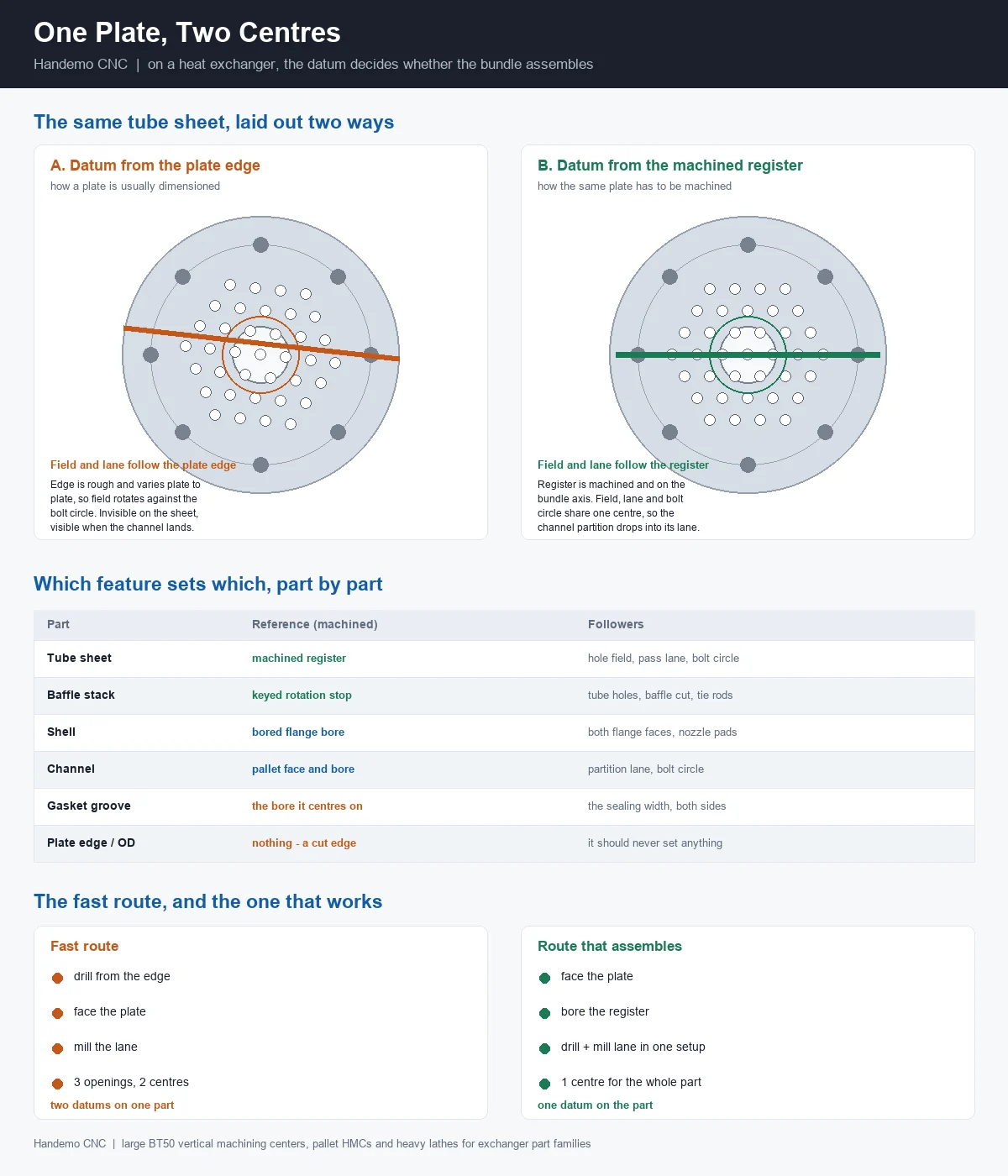
The plate arrives flame-cut, plasma-cut or sawn from a larger sheet. The edge is rough, it may have a rolled waviness from the plate mill, and its position relative to the intended centre varies by several millimetres from plate to plate. If the hole field is laid out from two edges, then every plate in the order has its field shifted and slightly rotated by whatever the edge did that day.
The shift is easy to miss because the first row of holes still passes a chordal check and the bolt circle still measures round. What changes is the angle between the field and the bolt circle. That angle is invisible on the tube sheet and it is exactly what the channel sees when it comes down on the gasket, because the channel's partition has to sit in the lane between two rows of tubes.
The practical fix costs nothing in machining time and everything in planning: face the plate, machine the register, and lay the field out from the register. Sequence becomes face, bore the register, then drill, rather than drill, then face. One extra decision at the CAM station, one less argument at the assembly bench.
The pass lane shares a datum with the bolt circle
On a two-pass or four-pass unit the lane that separates the passes is milled into the tube sheet. The partition plate drops into that lane, and the same partition is welded or keyed into the channel. So the lane and the bolt circle are not independent features: they are both measured from the bundle axis, and the channel's bolt holes are also measured from its own partition.
If the lane is milled in a second setup referenced from the plate edge, the part now carries two centres. That is not a machining error that can be corrected by a better operator; it is a sequence error, and the only cure is to do the lane and the field in the same setup, or to do both from the register in two setups but with the same reference.
The judgement worth carrying into a quote: two datums on one part is not a problem the drawing tightens its way out of, it is a drawing problem the shop inherits and pays for.
What a tube hole actually has to be
A tube hole is not a bearing bore. The tube is expanded into it with a roller, so the hole's job is to let the expansion produce the right contact pressure along the tube wall, and to survive the expansion without tearing.
- Size inside the expansion range for that tube wall. Too small and the roller cannot develop the wall reduction it needs; too large and the tube buckles or the joint relies on the weld only. This is a range, not a single number, and it comes from the tube supplier's rolling procedure, not from the plate drawing.
- A bore surface that has not been torn or work-hardened. A dull drill polishes and hardens the wall instead of cutting it. The roll then cannot bite, and the leak appears along one row, months later, at the plant.
- No burr on either face. A burr on the tube-entry side stops a tube going in or scratches it as it passes; a burr on the far side holds the tube off its seat. Both are removed by hand, and hand deburring is where a ligament gets eaten.
- The ligament between holes intact. The metal between two adjacent holes is the thinnest section on the whole part, and it is the path a crack takes from hole to hole. Heavy deburring on a soft material can remove a visible fraction of it. Deburr to break the edge, not to make the hole look polished.
Drilling Two Thousand Holes: Where the Time Goes
A tube sheet on a mid-size exchanger runs from a few hundred holes to well over two thousand. On a plate that size the machine spends more time travelling between holes than it spends cutting, and that single fact should decide how the job is quoted and which machine it goes on.
Per hole the cycle is: rapid to position, drill in, retract, rapid to the next. The cutting part is short because a tube hole is shallow relative to its diameter and the plate is usually between 20 and 150 mm thick. The rapid part is long because the holes are spread over a metre or two. A machine with a fast, stiff spindle and slow rapids will lose to a machine with an ordinary spindle and fast rapids on this part, and it is the opposite of what most buyers assume.
Peck, chip and the cost of a deep hole
In low-carbon plate the limit is chip evacuation, not power. A peck cycle clears the flutes but adds a retract and a re-entry per increment, and on a two thousand hole plate those retracts add up to hours. Through-spindle coolant or a parabolic drill that lifts the chip in one pass removes most of the pecks and is usually the difference between a two-day plate and a three-day plate.
Whatever the strategy, spot every hole on the first plate of an order. After that the spotting can be trusted, but the first plate is where a wandering drill will show you that the plate has a hard band or that the spot drill is not on centre. Finding that on hole one is cheap; finding it on hole nine hundred is a scrapped plate.
Tool life is counted in holes
A tube sheet is one of the few parts where tool wear is directly measurable: the drill either made four hundred holes or it did not. The same logic decides tool life on any large bore and housing part, where a worn edge shows up as a tapered hole rather than a broken tool. Keep the count on the job card and change on count, not on sound. The failure mode of a dull drill on a tube sheet is not a broken tool, it is a hole that is undersize at the entry and torn at the exit, in the last rows, after the operator has stopped watching.
Baffles: drill them as a stack
A bundle carries somewhere between ten and forty baffles of the same pattern. Drilled one at a time, that is forty setups with forty chances to load a plate rotated, and the tube holes are only as aligned as the worst of them. Clamped as a stack in a fixture with a keyed stop, they are aligned by construction, and the tube holes match because the same drill went through all of them in one pass.
The catch is thickness. Baffles are thin, often 6 to 20 mm, and they spring under clamp pressure. Clamp near the hole field rather than only at the corners, or the plate bows down under the drill and every hole entry becomes a shallow dimple that later has to be removed.
Baffle Rotation Is a Feature, Not a Detail
Segmental baffles have a cut segment, and the cut has to alternate along the bundle so the shell-side flow crosses the tubes instead of running straight down the shell. The rotation is defined by the cut and by the tie-rod holes, and it is a real feature of the part.
The failure is quiet. All the plates are drilled identically, which is what a stack fixture encourages. At assembly the fitter sees that the cuts all face the same way, flips every second plate, and the tube holes are now off pattern by the amount the plate is not symmetric about the flip axis. The bundle still goes together, the unit still holds pressure, and the duty is short for the rest of its life.
The cure belongs in the fixture: a keyed notch so a plate physically cannot be loaded in the wrong rotation, and a marking on the first article showing which side faces the shell inlet. It costs one slot in a fixture plate.
The Shell: A Rolled Cylinder Is Not Round
A shell is plate rolled into a cylinder with a longitudinal seam. Rolling leaves it oval, the seam shrinks as it cools, and the ovality is not the same at both ends. That means the outside diameter is not a reference for anything. Indicator readings taken on the OD tell you about the rolling, not about the axis.
So the sequence on a shell is: set it up on the bore, bore and face one end, then use that bore to set the other end. On a rolled cylinder that has to sit true in a frame, the setup problem is the same one covered in machining welded machine frames. The two flange faces end up square to the bore, which is the only genuinely round feature on the part, and square to each other, which is what the tube sheets at each end need.
Where the shell fits the bed, a heavy lathe does the job: the TCK80B-1500 turns to 800 mm maximum cutting diameter over 1,500 mm of cutting length with a 120 mm spindle bore and a 12-inch chuck, which covers the flange and nozzle work on small and mid-size exchangers. Where the shell is longer than that, or where both ends have to be bored in line, a horizontal machining center with a rotating pallet is the better answer: the part stays clamped once and the pallet indexes it, so the two ends share one setup instead of two.
That is the same argument as the tube sheet in a different form. The pallet rotation is not a convenience; it is what keeps both ends on one axis, which is the same reasoning behind machining multi-face parts on a horizontal center.
Gasket Faces: The Feed Pattern Decides Whether It Seals
A gasket seals on a contact pattern, not on a finish number. Two faces can look identical to the eye and to a profilometer and behave differently, because what matters is whether the tool left a continuous path from the inside diameter to the outside.
A spiral or plunge feed leaves exactly that: one groove that runs from the bore to the rim, crossing the whole sealing width. It is the same reason a flange bearing housing is judged on the face it seats against rather than on the diameter everyone measures. Under a spiral-wound or graphite gasket it is a leak channel, and it will weep at the hydro test on a joint whose bolts are correctly torqued. A concentric pass or a cross-hatch breaks the path at every revolution, so no single groove spans the seal.
The same logic applies to grooves. A tongue-and-groove or ring-joint face uses the groove to centre the gasket, so the groove has to be concentric to the bore that centres the mating part, not to the outside diameter and not to the bolt circle. Cut the groove in a second setup referenced from the bolt holes and the gasket sits off centre; one side of it then carries no load and the joint leaks on that side only.
The rule that covers both cases: cut the sealing face in the same setup as the register the mating part centres on. If that is not possible, accept that two setups means two centres, and make the second one follow the first deliberately rather than by convenience.
Materials, and What Each One Does to the Cut
- Carbon steel plate (SA516 grades) and forgings (SA105). Drills well but gummy at the low-carbon end, so a sharp edge and generous coolant matter more than coating. The common error is running a drill that has already done steel plate on a stainless part next, because the edge that survives carbon steel is not the edge stainless needs.
- 304 and 316L stainless. Work-hardens under a rubbing edge. A drill that dwells polishes the wall, the wall hardens, and the next pass breaks the edge off. Feed through the hole and keep the tool moving.
- Duplex 2205. Harder and more heat-sensitive than the austenitics. Lower surface speed and a higher feed per revolution, and never let the tool sit and rub: once duplex work-hardens, the hole is a fight.
- Titanium-clad tube sheets. Two materials in one hole. The clad side is the tube side and it is the side that must not be contaminated; the transition between clad and backing steel is where a drill wanders, and it is the row that leaks if the hole is off.
- Copper alloys: naval brass, aluminium bronze, cupronickel. Soft and grabby. They want a different drill geometry and a different feed from steel, and they punish anyone who reuses a steel drill because it was the right diameter.
Machine Choice by Part, Not by Size
Buyers usually ask for the biggest machine that fits the plate. The better question is which feature has to be machined in one setup, because that decides the machine more than the plate's diagonal does.
| Machine | What it gives you | What it is for on an exchanger |
|---|---|---|
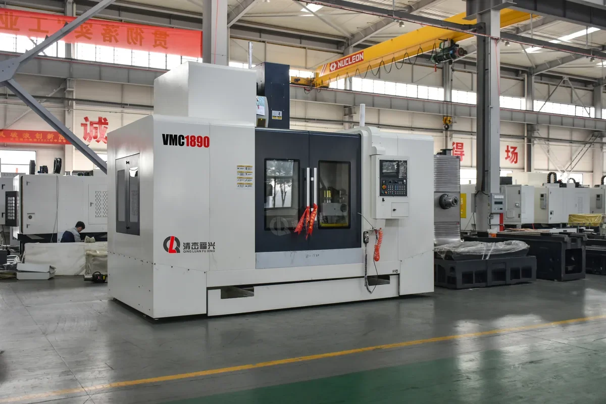
| VMC1890 | 2,000 x 900 mm table, 1,600 kg table load, 1,800 / 900 / 600 mm travels, BT50-190 spindle to 6,000 rpm, 14,000 kg machine | A tube sheet with a bolt circle inside the 1,800 mm X travel, drilled with 25 to 32 mm tools in stainless. The BT50-190 nose is what carries those tools without the drill chattering at entry. |
| VMC1690 | 1,600 x 800 mm table, 1,500 kg load, 1,600 / 900 / 700 mm travels, BT50-190 spindle | Mid-size tube sheets, baffle stacks, channel covers and pass partition plates, where the extra 100 mm of Z is worth more than more table. |
| TH1400S | 1,400 x 1,400 mm pallet, 5,000 kg load, 1,800 / 1,300 / 1,500 mm travels, BT50-45 degree spindle | Shells and channels bored and faced from both ends with one clamp, using pallet rotation instead of a second setup. |
| TCK80B-1500 | 1,000 mm swing, 800 mm cutting diameter, 1,500 mm cutting length, 120 mm spindle bore, 12-inch chuck | Shell flanges, nozzles and tube-side rings where the part is round and the work is turning. |
| TCK6350B | 630 mm swing, 96 mm spindle bore, 500 or 1,000 mm cutting length | Smaller exchanger flanges, tie-rod spacers and bar-fed rings. Buy it for the casting weight, not for the swing. |
Two things are worth saying plainly about this table. First, a high top spindle speed is close to worthless on a tube sheet: the drill runs slow and the travel runs long, so rapid speed, thrust and rigidity pay and rpm does not. Second, the machine that wins the quote is often the one that keeps the most faces in one setup, not the one with the largest envelope, because the setup is what puts two centres on a part.
What to Send With the Enquiry
Exchanger work is quoted from a drawing and a specification, and about half the questions that decide the price are not on either. These are the ones that change the process:
- The tube hole layout with its datum called out, or a line saying that the datum is the shell-side register.
- Tube outside diameter and wall, and whether the joint is expanded, welded, or both. The expansion procedure sets the hole size range.
- Plate thickness, and whether the tube side is clad or weld-overlaid.
- Baffle count, baffle cut and the tie-rod arrangement, or a section through the bundle.
- Gasket type: spiral wound, graphite sheet, or ring joint. It decides whether the face is flat, grooved, or conical.
- Number of passes. On anything above one pass, the pass lane drawing, because the lane is the feature that has to agree with the channel.
- For a retube or a replacement part: whether the part has to fit the existing shell. If it does, the worn part or the measured shell bore is the datum, and the drawing is only a guide.
Frequently Asked Questions
Can you drill a tube sheet from a PDF layout?
Yes, provided the layout carries a datum. If the only dimensions run from the plate edges, the first operation is to establish the register and re-reference the layout to it; otherwise the field will be correct to itself and off the bolt circle. Send the native drawing if you have it, and a note saying which feature is the datum if the drawing is ambiguous.
What is the largest tube sheet you can machine?
The VMC1890 takes a 2,000 x 900 mm table at 1,600 kg, which covers most shell-and-tube tube sheets up to a bolt circle inside the 1,800 mm X travel. Plates beyond that go on a boring mill or on a custom fixture, and the honest answer on a very large plate is that the fixture and the lifting are the project, not the machining.
Do you drill the tube holes or bore them?
Drill, then prepare the hole for the expansion the tube supplier specifies. Boring is used for the register, the pass lane and any groove, because those are the features that have to be on the axis. Boring two thousand tube holes is slower and buys nothing the roll does not already do.
Can you match a replacement tube sheet to a worn shell?
That is the normal case on a retube, and it inverts the process: the shell bore is measured and becomes the datum, and the tube sheet is machined to it. A replacement made strictly to the original drawing often will not fit a shell that has been in service for fifteen years.
How do you stop a gasket weeping on the first hydro test?
Three things, in order: cut the sealing face in the same setup as the register, use a feed pattern that does not leave a groove running across the seal, and make any gasket groove concentric to the bore rather than to the outside diameter. A face that measures flat can still leak if the tool left a path.
Do you machine the baffles and the channel as well?
Yes, and they should come from the same shop as the tube sheets if the bundle has to assemble. Baffles are drilled as a stack with a keyed rotation stop, and the channel is machined on a pallet so the partition lane and the bolt circle come from one setup.
Can you work from a worn part instead of a drawing?
Yes, and on exchangers it is often the better input. A worn tube sheet shows where the bundle actually sat, which is not always where the drawing said it should. Send photographs with a scale and the mating parts where possible.
Talking About a Real Part
A customer sent a drawing for a two-pass tube sheet, a stack of fourteen baffles and a channel, all for one unit, and asked for a price per set. The drawing gave the hole field from the plate edges and the bolt circle from the centre, which is a common way to dimension a plate and a poor way to machine one.
We machined the register first, laid the field out from it, milled the pass lane in the same setup, and drilled the baffles as a stack with a keyed stop so the cut alternated by construction. The channel was pallet-machined so its partition lane and bolt circle came from one clamp. Nothing in that sentence is a precision claim; it is a statement about which feature was measured from which, and it is the part of the job that decides whether the set assembles at the customer's site.
More industry routes are collected under application guides, including construction machinery, agricultural machinery and pump parts. If you have an exchanger part family coming up, the fastest way to a useful answer is a drawing plus the two or three facts that are not on it: the tube and its expansion, the gasket type, and whether the part has to fit something that already exists. Send the drawing and those notes and you will get a process route back, not just a number.
Contact Handemo CNC | Email: sales1@handemocnc.com | WhatsApp: +86 135 6320 3038