CNC Machining 3C Parts: Heat Sinks and Cases
An anodising line rejects parts for reasons the machine shop never sees. A batch of aluminium heat sink plates comes off the mill, the first article passes, four hundred pieces are cut, and three weeks later a third of the batch comes back from the finisher with a note about flatness and handling marks. Nothing in the shop changed. Same machine, same program, same operator.
What changed is that the plate was never flat. It was clamped flat. Release the clamps and the extrusion returns to the shape it had before machining, a shape it learned while sitting in a rack for six months. The mill proved the plate could be held straight, not that it was straight.
That is the pattern behind most 3C machining problems: the part measures correctly while it is still in the fixture and stops being correct somewhere between the fixture and the customer. This article covers the parts we see in consumer electronics work, the aluminium they are cut from, the order to machine them in, and the machines that suit each family. It sits with the other industry write-ups in our application guides.
What 3C Work Actually Means in a Machine Shop
3C is shorthand for computer, communication and consumer electronics, and in a machine shop it turns into four families of parts that behave very differently on a machine.
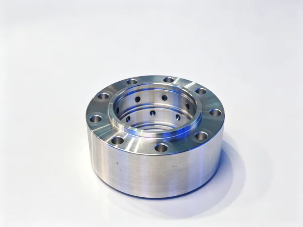
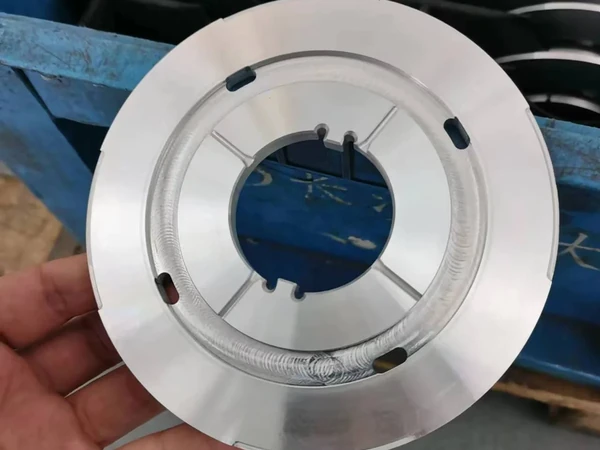
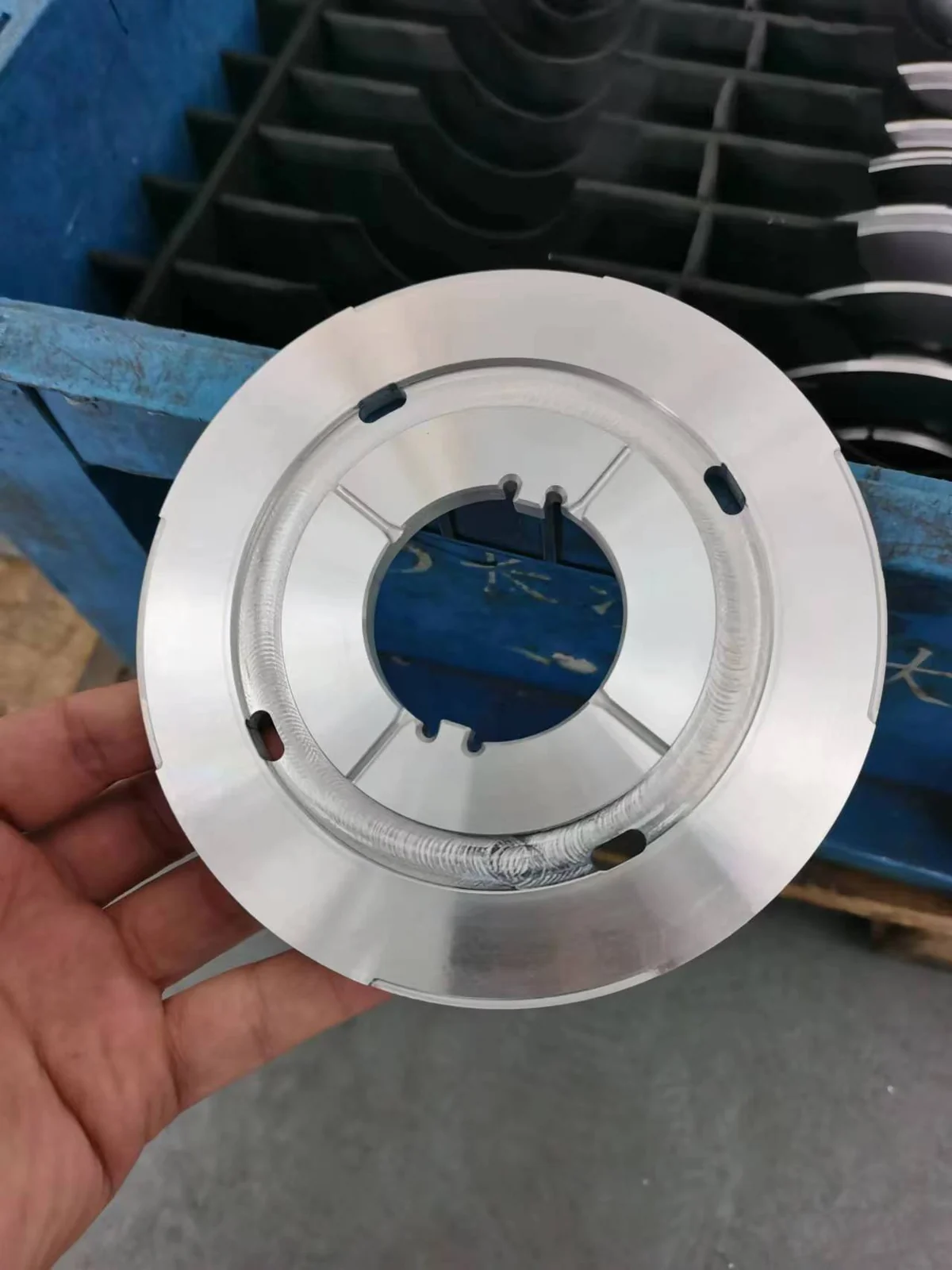
The first family is thermal: heat sinks, cold plates, heat spreaders and the mounting hardware around them. These are aluminium, they have fins or pin arrays, and their whole job is to be flat against a chip or a die and to move heat out of a sealed box. Fin geometry is usually the reason the part exists; flatness is usually the reason it gets rejected.
The second family is the shell: enclosures, chassis, bezels, camera housings, speaker boxes and the covers that close them. These are thin-walled, often five-sided, sometimes die-cast rather than machined from solid, and they have to look right as well as fit right, because the customer sees the outside.
The third family is structure: mid-frames, brackets, stiffeners, hinge blocks, connector housings. These carry small holes, fine threads and tight relationships between features that are far apart on the part.
The fourth family is tooling for the other three: test fixtures, nesting plates, pallets, soldering carriers and reflow boats. A shop that machines 3C parts for long enough ends up making its own fixtures, and those fixtures are usually the most demanding flat plates in the building.
What all four have in common is size and material. Parts are small, batches are large, the material is aluminium or a light die-casting alloy, and the cycle is short enough that handling and clamping time becomes a real share of the cost. A 90-second cycle with 40 seconds of loading is a machine running at 70 percent, no matter what the spindle does.
The Materials, and What Each One Does to the Process
6061 in T6
The default for machined 3C parts. It cuts cleanly, takes a thread, anodises to a predictable colour and is available in plate and extrusion. Its weakness is residual stress: a plate machined on one side only will bow as material is removed from that side, and the bow grows with the size of the plate and the amount of stock removed. Stress-relieved plate costs more and saves more than it costs on any part larger than a hand.
5052 and 5754
Softer, tougher, better for formed sheet parts and for enclosures that get bent after machining. It cuts with a built-up edge if the tool is not sharp and the coolant is not generous, and it marks easily. Any shop cutting 5052 for a visible surface should treat handling as part of the process, not as something that happens afterwards.
7075
Used where the part is structural and thin: internal frames, camera modules, hinge plates. It machines well and behaves badly after machining if the wrong temper is bought, and it does not anodise to the same cosmetic finish as 6061. Expect to explain that to a customer once.
Die-casting alloys
ADC12 and its relatives arrive as a casting, not as a plate. The machining allowance is small, the skin is hard and abrasive, porosity sits where the die decided it would, and clamping has to work around thin ribs that were never designed to be squeezed. A die-cast housing is a different job from a machined housing even when the drawing looks similar.
Heat Sinks: Fins Are a Chip Problem Before They Are a Drawing Problem
A heat sink with a fin field is a pocketing job where the pockets are deep, narrow and numerous. The tool has to reach the bottom, the chips have to leave, and the walls have to stay where the program put them. Most failures in heat sink machining are chip failures: a packed slot, a recut chip, a broken end mill, a scrapped part.
Fin aspect ratio decides the tool
The ratio of fin height to the gap between fins sets everything. Generous gaps allow a normal end mill with normal flute geometry and a normal feed. Tight gaps force a long-reach small cutter, which deflects, which means lighter passes, which means more time and more heat in a thin wall. A shop should quote from the drawing's gap dimension, not from the fin count.
Rough the field, then finish the walls
Clear the bulk of the material between fins with the largest cutter that fits, leaving a consistent allowance on the walls, then finish the walls in one continuous pass per gap. Trying to take the field and the finish in one operation is what produces tapered fins and a floor that is not flat.
Air blast beats flood on fin fields
Flood coolant carries chips back into the slot on a deep, narrow gap. Programmed air blast, or through-spindle air, clears the gap and lets the cutter cut instead of rub. Where coolant is required for heat, use high pressure and a tool with internal channels rather than a directed nozzle that cannot reach the bottom of the field.
The base is the part that matters
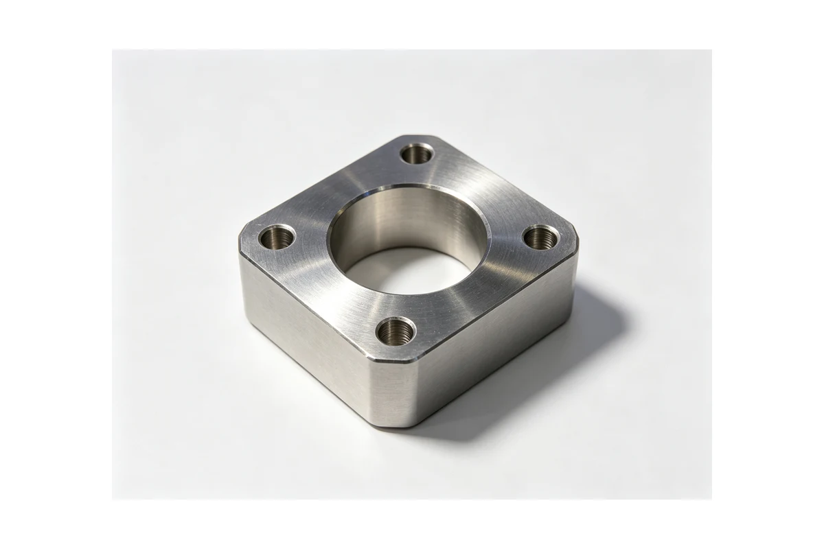
The mounting face has to sit against a die or a cold plate with no gap. That means the base is machined in a separate operation from a stable datum, and the fin field is machined afterwards so that the release of stress in the base does not happen after the base has been finished. Shops that machine the base last tend to be the ones that get flatness complaints.
Enclosures and Chassis: Five Faces, One Datum
An enclosure starts as a block or a casting and ends as a box with one open side, walls around a millimetre or two, a pocket for a board, and a set of holes that have to line up with a lid, a connector and a display.
The instinct is to machine it in two setups: outside first, then flip and hollow it. That works until the walls start to move. A better sequence for most enclosures is to establish the open face and the inside first, because the inside is where the datums for the board and the connector live, then hold the part on the finished inside geometry for the outside work.
Clamping is the whole problem
A thin wall deflects under jaw pressure and springs back when released. Machining the wall while it is pressed in produces a wall that is thick in the middle and thin at the ends once the pressure is gone. The fix is either to support the wall from inside with a close-fitting nest, or to clamp on a solid feature and never on a wall that will end up thin.
Corners and radii
Internal corners on an enclosure usually have a radius on the drawing because the cutter has one. Where the radius is a functional requirement, for a board corner or a gasket, it pays to leave the corner in the roughing operation and finish it with a smaller tool afterwards rather than let the roughing tool define it.
Cosmetic faces need their own rules
Any face that will be visible after finishing should not be used as a clamping surface and should not be touched by a chuck or a vice jaw. Where it must be held, use soft jaws bored to the part, or a vacuum plate, and cover the surface with a sacrificial film for handling between operations.
Mid-Frames and Long Thin Parts
A mid-frame is a long, narrow plate with a perimeter profile, a set of pockets, and a large number of small holes, often with M1.6 or M2 threads. Its failure modes are different again: the part bends along its length, and the taps break.
Support the length
A long thin plate clamped at two ends will vibrate in the middle. Support it from below with a nest machined to the part profile, or hold it on a vacuum plate with a gasket groove that follows the perimeter. Both approaches let the cutter work in the middle of the part without the plate singing.
Tapping small threads
Small threads in aluminium fail for three reasons: the hole is undersized because the drill wandered, the chip is not cleared, or the tap is dull and the operator keeps going. Program a peck tap, use a spiral-flute tap for blind holes and a spiral-point for through holes, and check drill runout on the machine before the run rather than after the scrap. Thread depth control matters more than thread speed: a tap that bottoms in a shallow hole breaks in a way that costs the part and, often, the fixture.
Hole-to-hole relationships
When a frame carries thirty holes that must line up with a die or a casting, they should all be drilled in one setup with one origin. Splitting them across two operations means the two sets are positioned relative to two different datums, and the error appears at assembly, which is the worst place to find it.
Die-Cast Housings: Clamp on the Right Three Points
A die-cast housing arrives with a skin that is harder than the material inside it, edges that are thicker than the walls, and ribs that exist to stiffen a part that was never designed to be clamped.
Find the machining bosses
Die castings usually have pads or bosses intended for clamping and for the machining datum. Use them. Clamping across a rib puts a mark on the finished surface and a bend in the casting that stays there after release.
Expect porosity and plan for it
Porosity shows up as a void in a machined face, usually on the last part of a batch, usually on a face that has to be sealed. The process answer is to machine the sealing face early in the sequence, so a leaking casting is discovered before the part has absorbed four more operations.
Cut the skin with a fresh edge
The as-cast skin is abrasive and will wear a cutter faster than the same volume of solid aluminium. Keep a tool reserved for the first pass on cast surfaces and change it on a count, not on a feeling.
The Order of Operations That Survives Anodising
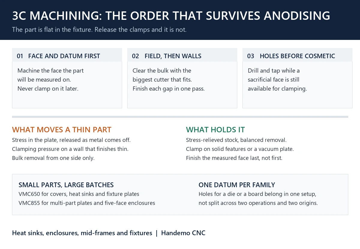
Anodising does not change dimensions much, but it does remove the evidence of everything the shop did wrong before it. Three rules cover most of it.
First, finish the face that the part will be measured on before the operations that remove a lot of material. Removing bulk from one side of a stressed plate releases the stress and moves the opposite face.
Second, never drill or tap a finished cosmetic face at the end of the sequence. Do the holes while the part still has a clamping surface that can be sacrificed, then finish the cosmetic face in a separate light operation if the drawing allows it.
Third, deburr before the part leaves the machine, not after. A hand deburr on a thin edge rounds it unevenly and creates a surface that anodises to a different shade. A programmed chamfer pass on the edges that will be visible is faster and more consistent than any amount of bench work.
Fixtures: Vacuum, Soft Jaws and Multi-Part Plates
Vacuum plates
For flat plates and thin covers, a vacuum plate with a gasket groove cut to the part outline gives uniform clamping with no local pressure. It is the closest thing to machining a part with no fixture at all. It needs a clean, flat back face, a gasket that actually seals, and a vacuum pump sized for the leakage of the setup, not for the pump's label.
Soft jaws bored in place
For round and near-round parts, jaws bored in the machine at the pressure that will be used for the run give a firm grip with no marks. Bore them at the same pressure, because a jaw bored at high pressure and used at low pressure grips on two points instead of three.
Multi-part plates
Where the part is small and the batch is large, machine a plate with twelve or twenty nests and cut the whole plate in one cycle. The economics are obvious; the discipline is less so. Every nest has to be positioned from the same origin, and the plate has to be stress-relieved before the nests are cut, or the plate will bow and the parts at the ends of the plate will be cut at a different depth from the parts in the middle.
Choosing the Machine
Three sizes cover most 3C work, and the choice is driven by part envelope and by how many parts the fixture has to hold at once.
The compact end
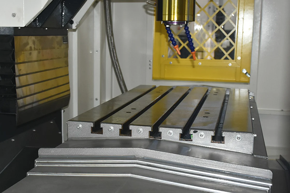
The VMC650 carries a 1000 x 400 mm table rated to 400 kg on a 3,800 kg casting, with 650 / 400 / 550 mm of travel and 32 m/min rapids in X and Y. Its BT40 spindle runs to 8,000 rpm with a 16-station disc changer and a 2.5 second tool change. For heat sinks, small covers, fixture plates and electrodes it is the right size: small enough to accelerate quickly, heavy enough not to ring when a long-reach cutter is working in a fin field.
The middle
The VMC855 moves up to a 1000 x 550 mm table at 600 kg, with 800 / 550 / 550 mm of travel, a BT40-150 spindle at 8,000 rpm and a 24-station changer on a 5,300 kg casting. This is the size where a multi-part plate becomes practical: a plate with eight enclosure nests still fits, and the 24-station magazine lets a program carry roughing, finishing, drilling, tapping and chamfering tools without an operator touching the machine.
The larger end
The VMC1160 takes a 1200 x 600 mm table rated to 800 kg, with 1100 / 600 / 600 mm of travel, a BT40 spindle with a 150 mm nose at 8,000 rpm, a 24-station changer and a 6,500 kg casting on box ways. It is the machine for large chassis, long mid-frames and plates that need several parts per cycle, and the extra mass is what keeps a long thin part from vibrating in the middle of the table.
When the finish is the product
Where the visible surface has to come off the machine finished, a high-speed machine with a faster spindle and a thermally controlled structure does the last operation better than a general-purpose VMC. For 3C work this usually means the high-speed mold machining centers, used for the cosmetic pass and for electrode work rather than for roughing.
Two more choices affect the result more than the model number. A 4th-axis rotary table turns a five-face enclosure into two setups instead of four, and the difference shows up in the position of the holes on the fifth face. And a BT40 spindle is the correct default for aluminium 3C work: the parts are small, the cutters are small, and the extra mass of a BT50 buys nothing that the part needs.
Cutting Tools and Coolant Discipline for Aluminium
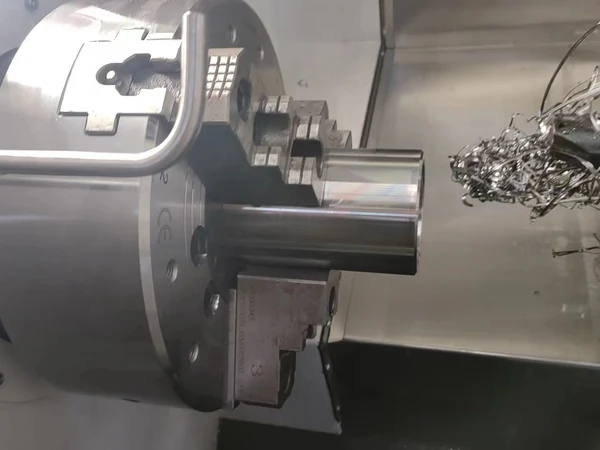
Aluminium is soft, which makes it sound easy, and sticky, which makes it difficult. The two facts together explain most of the tooling rules.
Sharp, polished, uncoated or lightly coated
For aluminium, a polished flute and a sharp edge beat a hard coating. Where a coating is used, it should be one that does not react with aluminium; a tool designed for steel will weld aluminium to its edge and then tear the surface it was meant to finish. Keep a separate set of tools for aluminium and never let a tool that has cut steel touch an aluminium cosmetic face, because embedded steel particles become a stain after anodising.
High speed, moderate feed, big chip
Aluminium wants surface speed and a chip thick enough to carry heat away. A light pass at high speed rubs, work-hardens the surface and produces a finish that looks burned after anodising. Program a real chip load and let the spindle do the work.
Coolant, air and cleanliness
Use coolant that is clean and correctly mixed, and keep the concentration where the supplier says. Stale coolant leaves a residue that shows up as a patchy finish. For fin fields and deep pockets, air blast is often better than flood. Before the part goes to the finisher, it should be washed and dried, and it should not be handled with bare hands: fingerprints are a finishing defect, not a cosmetic detail.
Inspection and What to Check Before the Finisher
Every 3C part should be checked twice: once in the fixture, where the machine can still correct it, and once out of the fixture, after the clamps are released and the part has had time to move.
The in-fixture check confirms the program. The released check confirms the process. A part that measures well in the fixture and badly on the surface plate has a clamping or sequencing problem, and no amount of program editing will fix it.
For thin parts, check flatness on a surface plate with a light touch, and check it again after the part has sat for a shift. Aluminium continues to move for a while after machining, especially when a lot of material came off one side, and a part that is flat at the end of the cycle is not necessarily flat at the packing bench.
For enclosures, check the wall thickness at several points rather than one, check the position of the connector cutout against the board datum, and check that the lid sits without a gap on a flat surface. That last check catches more real problems than any single dimensional reading.
Volume, Lights-Out and the Point Where Automation Pays
3C work is volume work, and volume changes what the machine has to do. At a few hundred parts a month, a VMC with a good fixture and an operator is the correct answer. At tens of thousands, the constraint moves from the spindle to the loading.
The first step is usually a multi-part plate, because it costs a fixture and a program and multiplies the output of every cycle. The second is a pallet change or a shuttle table, so the machine keeps cutting while parts are swapped. The third is automated loading, and for small parts on a lathe or a VMC that usually means a robot or a gantry loader rather than a bigger machine.
Before any of that, standardise the workholding. Automation multiplies whatever the fixture does; if the fixture needs a manual jaw change between part families, the automated cell will need an operator standing next to it, and the investment case disappears.
The economics also depend on scrap. A cell running unattended at three in the morning will keep cutting a bad part until something stops it, so tool life monitoring and a simple in-process check on a critical feature are worth more in a 3C cell than in a job shop running one-offs.
Frequently Asked Questions
Why do aluminium parts move after machining?
Because the material had stress in it before the cutter arrived. Rolling and extrusion leave residual stress in a plate or a profile, and removing material from one side unbalances it. The part then bends to find a new balance. Stress-relieved stock, balanced material removal from both sides, and finishing the critical face after the bulk removal all reduce the movement.
Should a heat sink be machined before or after the fins?
Machine the mounting face first from a stable datum, then cut the fin field. If the fins are cut first, the release of stress in the base happens afterwards and the finished face is no longer flat when the part reaches the customer. The exception is a part where the fin field is the datum, which is rare.
How do you hold a thin-walled enclosure without crushing it?
Clamp on a solid feature, never on a wall that will finish thin, or support the wall from inside with a nest or a close-fitting insert. Soft jaws bored in place at the pressure used for the run work well for round parts. For flat covers, a vacuum plate with a gasket groove gives even pressure with no local marks.
Can a general-purpose VMC handle 3C work?
Yes, for most parts. The limits are spindle speed for very small cutters, thermal stability for long finishing passes, and the number of tools in the magazine when a program needs roughing, finishing, drilling, tapping and chamfering in one cycle. A 24-station magazine and an 8,000 rpm BT40 spindle cover a large share of 3C parts.
Why do tapped holes in aluminium fail?
Usually because the drill wandered, the chip was not cleared, or the tap was dull and the cycle kept running. Peck tapping, the right flute geometry for blind or through holes, and a check on drill runout before the run prevent most of it. Thread depth should be programmed from the drawing, not estimated at the machine.
What has to be true before parts go to anodising?
The part should be flat when released, deburred on every edge, washed and dried, and free of steel contamination from tools that also cut steel. Handling marks and fingerprints become finishing defects, so parts should be handled with gloves or in bags from the last operation onwards.
Where Handemo Fits
Handemo has been building machine tools in Tengzhou, Shandong since 2008, on a 220,000 square metre site with more than 660 employees, and ships to customers in over 150 countries. The 3C work we see most often is aluminium: heat sinks, covers, frames and the fixtures that hold them, cut on vertical machining centers from the VMC650 up to the VMC1160, with 4th-axis tables and multi-part plates where the volume justifies them.
If you are quoting a 3C part family and want to know which frame size and fixture arrangement makes the cycle work, send the drawing, the material, the batch size and what has to line up at assembly. We will come back with a machine size, a workholding proposal and a sequence, and we will say so if a different machine type is the better answer.
Contact Handemo CNC | Email: sales1@handemocnc.com | WhatsApp: +86 135 6320 3038