CNC Machining for Textile Machinery Parts
The enquiry came in as a photo of a roller, lying on a bench next to a steel rule. Two hundred of them, for a warp knitting machine, and the customer's complaint was short: the bearings keep going. The rollers were round, the journals were the size the drawing asked for, and the bearing seats at each end had been measured before the parts left. What the customer had not measured was whether the two bearing seats at either end of a 900 mm roller were on the same axis as each other. On about a third of the batch they were not, and a shaft that is turned between two settings without a common reference will do exactly that.
Textile machinery is full of parts like this roller: long, slender, cheap per piece, and running all day at speeds that punish anything that is not straight. A spinning frame, a weaving loom, a knitting machine or a finishing line is not a machine tool, and the parts that keep it running are not exotic. They are rollers, spindles, cams, guide bars, bearing seats, brackets and frames, and most of them are round. What makes them awkward is not the material. It is the ratio between length and diameter, and the number of surfaces that have to agree with each other along that length.
This is a guide to the textile machinery parts we get asked about most: what each family has to do, which surfaces have to share an axis, where the process usually goes wrong, and which machine ends up doing the work. It sits alongside the other application guides we have written for packaging, food and beverage, agricultural and construction machinery, because the parts overlap and the thinking is the same.
The parts that come through a textile machine shop
Four families account for most of the work, and they fail in different ways.
Rollers and roller shafts
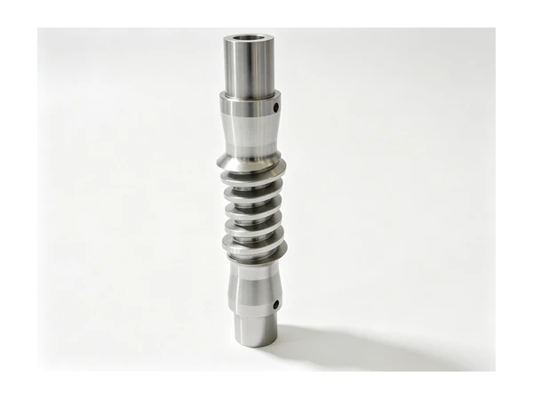
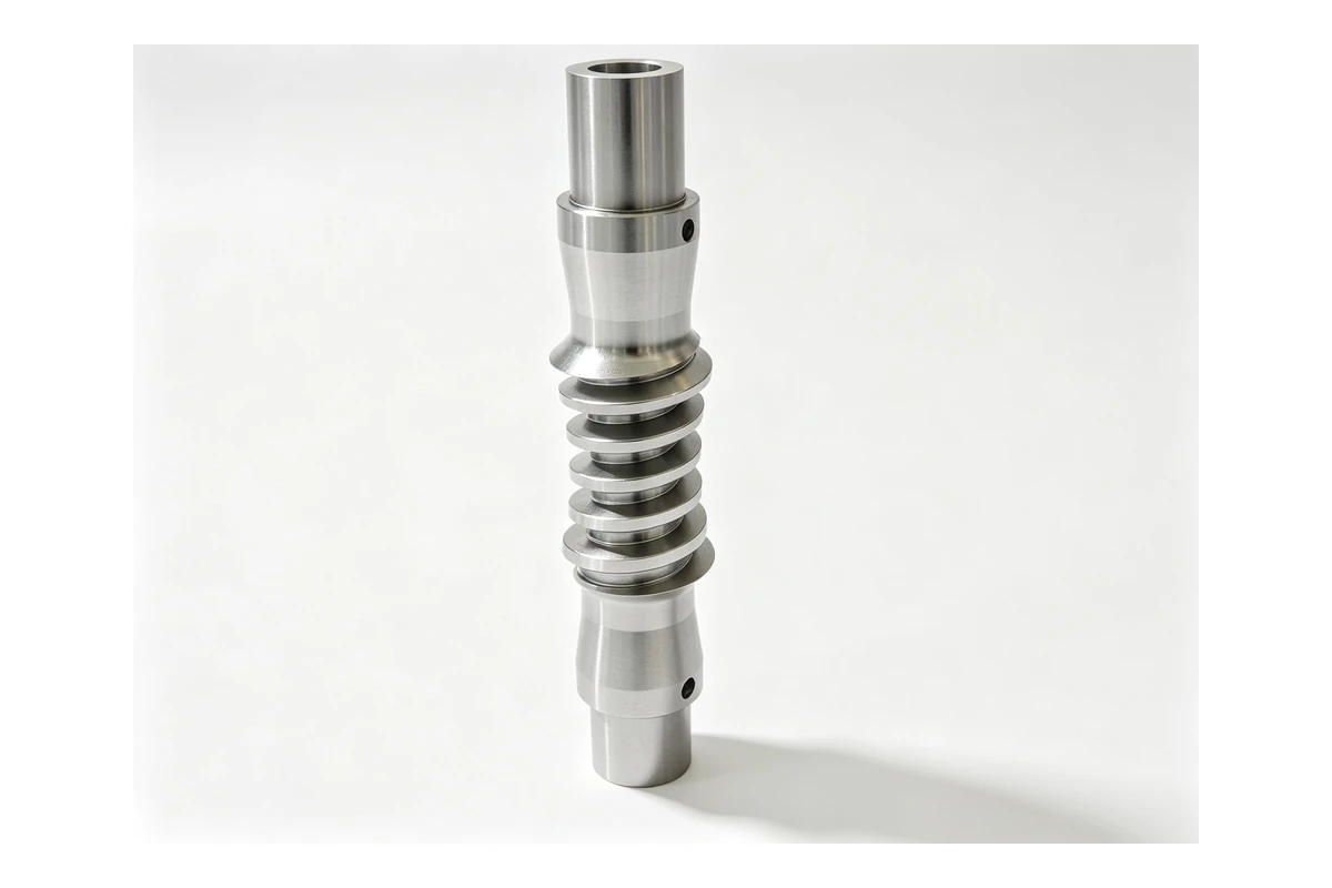
A roller is either a tube mounted on a shaft, or a one piece body with journals turned on each end. In a spinning frame, a draw frame or a warping machine these are the parts that carry yarn or fabric, and there are hundreds of them in one machine. The length to diameter ratio is the whole story: a roller 900 mm long and 60 mm across is fifteen times longer than it is wide, and it will deflect under its own weight when it is held at one end. Two bearing seats, one plain journal, often a keyway for a gear or a pulley at the drive end, sometimes a spiral groove turned into the surface.
Spindles and small rotating shafts
Spinner spindles, spindle tapes drive shafts, godet shafts, twist spindles. These are shorter but run faster, and they often carry a taper or a seat that a small tool holder or a bobbin sits on. A spindle is a turning job with a milling job on the back of it: a keyseat, a flat, a cross hole or a slot for a pin.
Cams, eccentrics and cam tracks
A camshaft in a loom or a knitting machine is a shaft with a set of profiles on it, each one at a fixed angle to the others. The profiles lift and drop the heddle frames, the needles, the sinkers or the guide bars. The whole part is a timing device, so what matters is not the shape of any single profile but the angle between them, and that angle has to come off the shaft the cams turn on.
Bearing seats, housings, brackets and frames
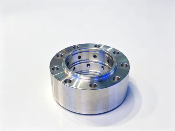
Cast iron or aluminium seats for the roller bearings, pillow block housings, guide bar brackets, tensioner arms, machine frames and side plates. These are the parts that decide whether everything else lines up, because a roller shaft can be perfect and still run wrong if the two bearing seats that hold it do not share an axis.
Materials, and what the material does to the plan
The material list for textile parts is short, and each one has one thing about it that changes the route.
Medium carbon steel, 1045 in most cases, is the default for roller shafts, spindles and general shafts. It turns cleanly, it holds a keyseat, and it is the material a shaft job is quoted in when the drawing does not say anything else. Pre-hardened alloy such as 4140 appears where the part is also a drive component. It is tougher, and because it arrives already hard the finishing passes are lighter.
Aluminium, usually 6061 or 6082, is what textile machinery tends to use for guide bars, brackets and moving parts where weight matters. The problem with aluminium on a long part is not the cutting, it is the movement: a slender aluminium roller or guide bar will move while it is being machined because there is nothing holding it in shape, and it will move again after the cuts are finished. The practical answer is to rough it, let it sit, and finish it in a second pass rather than to push a light cut through and hope.
Cast iron, GG25 or a similar grade, is still what the housings, seats and frames are cast from. It damps, it comes in volume cheaply, and it leaves stock to clean up. The catch is at the first operation, because a raw casting has no round surface to indicate from. The outside has to be gripped, a face cleaned up and a datum established before anything else can be turned true to it. Castings also arrive with hard patches, which is what breaks an insert in the middle of an interrupted cut.
Stainless appears on wet finishing lines and anywhere a part sees steam, dye or washdown water. It work hardens if the tool rubs instead of cutting, so the pass has to get under the skin and keep moving.
Two conditions change the route without changing the shape. A part that is case hardened or nitrided after machining will move, so the bearing seats and the keyway have to be finished or re-cut after the furnace, not before it. A part that is hard chromed, which is common on rollers that see water, has to be left oversized for the plating and finished afterwards, which means planning the two settings around a further trip out of the shop.
Why a long roller is not just a short roller made longer
On a shaft of ordinary proportions, the deflection under cutting force is small enough to ignore. On a textile roller it is not, and this is the single thing that separates textile work from general turning.
Take a 900 mm roller with a 55 mm body and a 40 mm journal at each end, turned between a chuck and a tailstock. In that arrangement the part is supported at both ends and the middle is free, so the middle pushes away from the tool. Roughing at a sensible depth on a slender shaft makes a barrel, not a cylinder. By the time the part is finished, the middle is oversize in the direction the tool pushed, and the amount is different at each point along the length, so a single adjustment to the offset does not fix it.
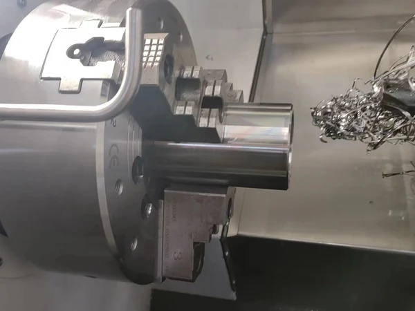
The answer is support. A steady rest, sometimes called a centre rest or a follow rest, is placed at or near the middle of the work and set on a surface that has already be turned. That gives the part a third support and takes most of the flex out of it. On a long roller the sequence is then: face and centre drill both ends, support on centres or in the chuck with a tailstock, rough turn the middle section, set the steady rest on that turned section, turn the journal on that side, then move the steady and repeat for the other end. It is more settings than a short shaft, and it is the only way the two bearing seats come out on one axis rather than two.
The alternative is a part that is turned, checked and found to be straight to the eye. A barrel of a few hundredths of a millimetre over the middle of a 900 mm shaft is invisible on a bench and audible in a spinning frame, because the roller is running at speed with a length of yarn on it and the deflection repeats once per revolution.
The two bearing seats have to be on one axis
Every complaint we get about a textile roller comes back to this sentence, so it is worth saying plainly: the two seats are one feature measured at two places, not two features that happen to be at the ends of the same part.
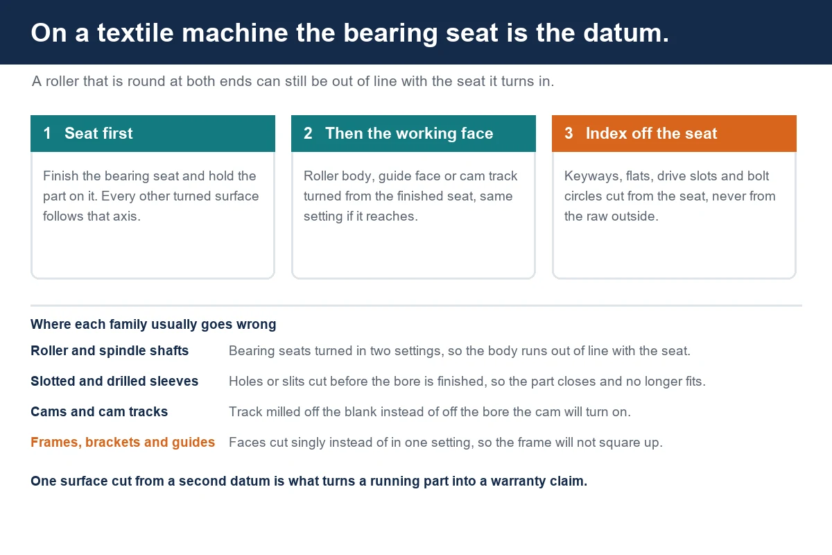
The route that produces that result is to fix the axis early and keep everything on it. Face both ends and centre drill them for the tailstock and the steady rest. Turn one bearing seat and use it as the reference for the body and for the second seat, with the steady rest set on the turned body rather than on the raw bar. If the part is too long to reach from one side, the second operation is set on the finished first seat, on centres or in a bored soft jaw, and never on the outside diameter of the body.
The failure case looks like this. The roller is gripped on the body and one seat is turned. The part is turned end for end, gripped on the body again, and the second seat is turned. Two things go wrong at once: the chuck has some runout, and the body has already moved slightly on its own because it is long and it was released from the first grip. The second seat is now concentric with the chuck rather than with the first seat. Each end measures correctly against the drawing. The roller wobbles when it is spun between centres, and the customer sees it as a bearing that fails early rather than as a shaft that was turned wrong.
Slender work: which machine helps and which does not
Length to diameter ratio decides the machine, and it decides it earlier than people expect.
Below a ratio of about ten to one, a roller is ordinary turning work and a standard slant bed lathe with a tailstock handles it. Up to about twenty to one, the part needs a steady rest and a careful sequence, and it still fits a lathe with a long bed. Past that, the part is a different job: the weight of the work itself starts to bow it, the speed has to come down, and the practical answer is often a hollow body slipped over the shaft as a damper, or a change in the drawing to a tube with pressed in journals.
The machines we put on textile roller work are the longer bed models. For a roller or spindle up to about a 500 mm turning diameter with a 65 mm spindle bore and 50 mm bar capacity, the TCK50 slant bed lathe covers it in an 8 inch chuck, with a tailstock for shafts and an 8 or 12 station turret. Longer and heavier rollers go on the TCK6350B, which has a 630 mm swing over the bed, a 96 mm spindle bore and an 85 mm bar capacity on an 18.5 kW spindle, and a 12 station servo turret that carries the boring bars and the steady rest work a roller job needs. Where the roller is long enough that a 500 mm cutting length is not enough, the TCK80B-1500 is the one we quote: a 1000 mm swing over the bed, 1500 mm of cutting length, a 120 mm spindle bore with 105 mm bar capacity, a 22 kW spindle motor and the same 12 station turret.
Cams, timing and the angle between the profiles
A camshaft for a loom or a knitting machine is a timing part, and the drawing is usually written as angles rather than as features.
The profiles on such a shaft have to sit at fixed angles to each other and to the keyway or the drive flat at the end. That means the process needs one datum for angle, and the datum is the shaft the cam turns on, which is the bearing seat or the finished bore, whichever the part has. Everything else is generated from that: the cams, the keyway, the pin holes and the drive flat.
The route that holds is to finish the bearing seats or the bore first, set the part on that datum on centres or on a mandrel, and then mill the profiles with the rotation indexed from the same datum. On a lathe with a C axis and driven tools this can be one clamping, with the cam profile milled by the live tool and the index coming from the spindle rather than from a fixture. On a vertical machining centre the part goes on a fourth axis or on a dividing fixture, set on the finished seat rather than on the outside of the bar, and the keyway is cut first so that every later index can be taken from it.
The failure case is the same one as on the roller. Milling the first cam off the blank, then the second cam off the blank, then the keyway off the blank, is three datums for one part. Each profile is the right shape and the angles between them drift, and a loom with drifting timing runs unevenly in a way that is hard to trace back to the shaft.
Where a cam track rather than a profile is involved, as on some guide bar drives, the track is a groove milled or ground around a finished bore, and it is indexed the same way. Our notes on eccentric shafts cover the related case of a part whose working surface is deliberately off the turning axis, which is a decision made on the drawing and not at the machine.
Slots, holes and splits: the cuts that release stress
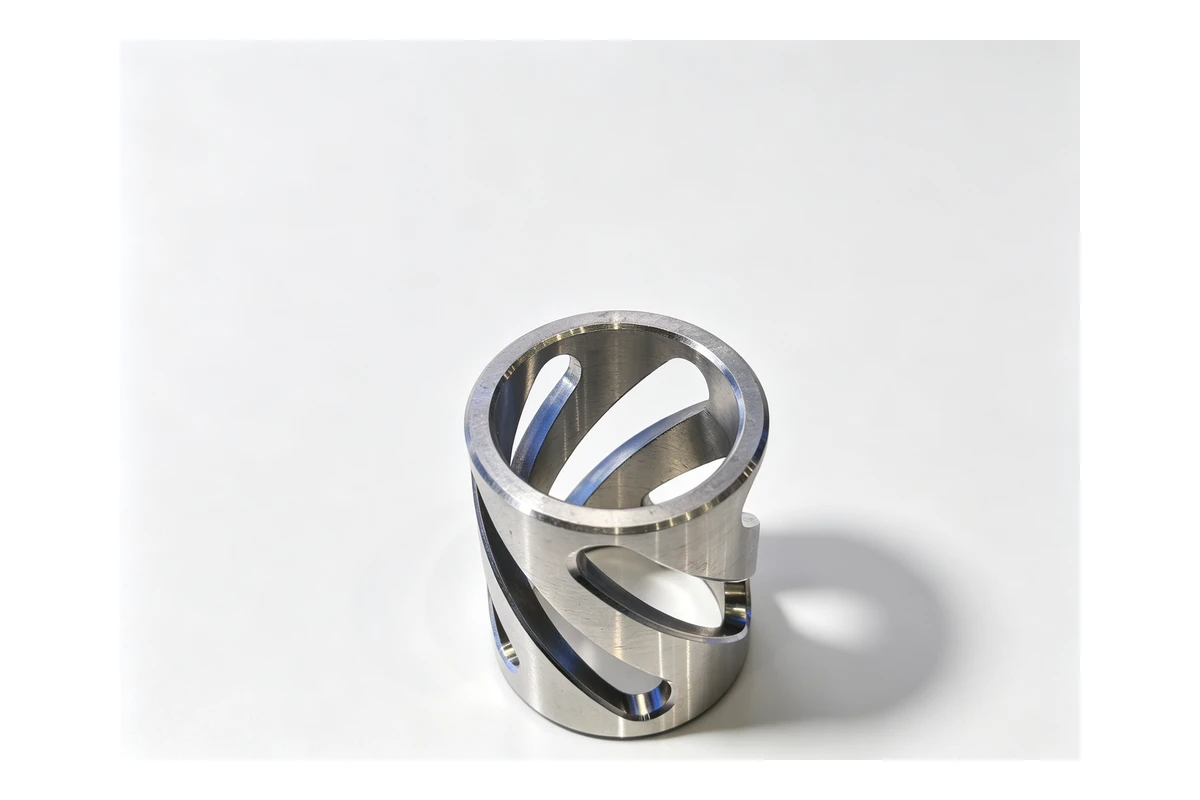
A large share of textile parts are sleeves, drums and bars with slots, holes, spirals or slits cut into them. These cuts are small in volume and large in effect, because removing material from a wall that is already thin releases whatever stress was holding the part round.
Two examples are common. A sieve or perforated drum starts as a thin wall tube, and the wall is drilled or milled in a pattern. If the bore is finished before the holes are cut, the holes relieve the wall, the bore closes slightly and the part no longer fits the shaft it was made for. The sequence that works is to rough the bore, cut the holes or slots, and finish the bore last, after the wall has moved. The second example is a slotted sleeve or a clamping bush with a slit down one side: the slit is a feature, and it has to be cut after the taper and the bore are finished rather than before, because the slit is what lets the part close on the shaft.
The same logic governs a drilled sleeve with a cross hole or a spiral groove turned on the outside. The cross hole is drilled from the finished bore if it is to sit where the drawing puts it, and the groove is turned with the part supported on the bore rather than held by the outside.
Housings, seats and frames: the parts that decide the rest
The parts that hold the rollers are the ones worth planning hardest, because their job is to put two bores on one axis across a distance.
A bearing seat or a pillow block housing has two bores, sometimes several, and each one holds a shaft that has to line up with a shaft in another housing somewhere else on the frame. That means the bores within one part have to share an axis, and the mounting face has to be square to it, and the pattern of mounting holes has to be indexed from the bore rather than from the edge of the casting. On a horizontal machining centre the part is set once on a pallet and the bores are machined from the same setting, so the relationship between them comes off the machine. On a vertical machining centre the same result needs either a fixture that indexes the part accurately or a second setting that is set on the first bore.
Plain housings and brackets rarely need the full treatment, but the ones that carry a roller at each end of a machine do. Where a family of brackets runs in batches, that is the case where a horizontal with a pallet changer earns its place, because the second face is cut while the first pallet is being loaded. Our comparison of vertical and horizontal machining centres for multi face parts and the guide to choosing a machine for box and housing work both cover how that usually comes out.
The machine we put on the larger frames and housings is the HMC1000, with a 1000 x 1000 mm table, a 3500 kg table load, 1300 x 1100 x 1200 mm of travel and a BT50 spindle. For a frame that has to be machined on several faces and is too heavy to move often, the TH1400S takes a 1400 x 1400 mm pallet with a 5000 kg load, 1800 x 1300 x 1500 mm of travel and a BT50 spindle. Brackets, plates and smaller seats go on a vertical: the VMC855 with its 1000 x 550 mm table, 800 x 550 x 550 mm of travel and 600 kg table load handles most of it, and the VMC1160 covers the larger plates at 1200 x 600 mm and 800 kg. Where a guide bar or a long bracket has to be drilled and milled along its whole length, the VMC1560 with a 2200 x 600 mm table and 1500 mm of X travel is the one that reaches.
Rollers with a drive end, and mill turn work
Many textile rollers are not plain. The drive end carries a gear, a pulley, a coupling or a sprocket, and the body carries a flat, a slot or a cross hole for a guide, a tensioner or a sensor.
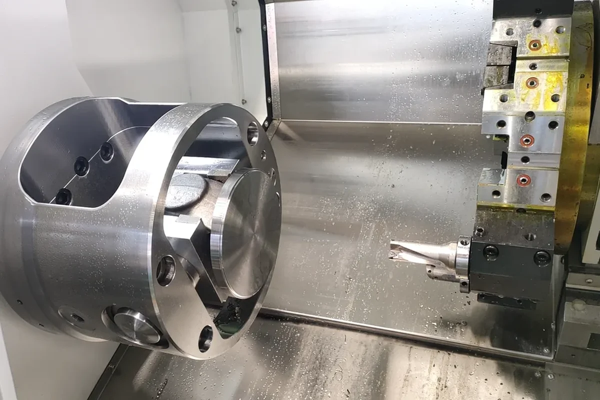
That combination is exactly the case for a mill turn machine, because it turns a two machine job into one. The bearing seat and the body are turned, and the keyway, the flat and the cross hole are milled in the same clamping, with the angle taken from the finished seat. The TCK6050Y is the machine we put on that work: a 560 mm swing, a 410 mm turning diameter, a 65 mm bore with 50 mm bar capacity, and Y travel of 50 mm either side of centre with two bed lengths. Where a roller or a spindle has to be machined at both ends, with the bore or the first seat finished and the opposite end turned from it, a dual spindle mill turn machine such as the TCK6050SY takes the part in one machine: a 67 mm and a 56 mm spindle bore, 50 mm and 45 mm bar capacity, 18.5 kW on each spindle and a Y axis with 50 mm of travel.
Running a batch of two hundred rollers
One roller that runs true is a job. Two hundred that all run true is a process, and the difference between the two is what drifts between the first part and the last.
Three things move over a batch. The chuck jaws wear and the grip pressure changes, which matters on a thin walled roller where the part is round in the chuck and out of round when it comes out. The turning insert wears, so the diameter creeps in one direction and every part that follows follows the same creep. And the machine warms up, so the parts turned at the start of a shift are not cut under the same conditions as the parts turned at the end, unless the offsets are checked at the start of the run.
The way to hold a roller batch together is the same as on any other part family, and it comes down to fixing the datum once. Finish the first bearing seat and hold the part on it for everything else. Set the steady rest on a turned surface, not on the raw bar. Check the finished roller between centres rather than on the outside diameter, because the outside is the surface the next operation will hold and it should not be the surface the part is judged from. Keep the shaft and the roller body together through the batch if the two are made as a pair. And if the customer wants the rollers in matched sets for one machine, keep each set together rather than finishing one roller fully before starting the next.
What decides the quote on a textile part
Textile work is quoted from the drawing, and the price is mostly about how many settings the part needs and how many surfaces have to be indexed from one another.
- The overall length and the largest diameter, because their ratio decides whether the part needs a steady rest.
- The number of bearing seats and journals, and whether they have to share an axis.
- Whether the part is turned from bar, from a tube or from a casting, and whether it is a hollow body on a shaft.
- The keyway, flat, slot or cross hole, and whether it can be cut in the same setting as the seat.
- The material and its condition, including whether it is pre-hardened bar or a raw casting.
- Whether the part is heat treated, hard chromed or plated, and in which order relative to the seats.
- The batch size, and whether the fixture is being made for the first time.
Send the drawing, the length, the material and the quantity, and the questions above are the ones we will come back with. If the part is a replacement for something that has failed in service, a photo of the old roller next to a rule is worth more than a dimension we would have to guess at, because the failure pattern usually says which setting went wrong.
Rollers, spindles, cams and the seats and housings they run in are the kind of work we do every week, and the related part families are covered in our machining solutions notes on bushings, sleeves and rings, transmission shafts and gears. Some of the harder ones are written up in full in our case studies, including the job on turning a long reducer shaft where the same slender shaft problem had to be solved. If you have a roller that will not run true, a batch that will not repeat, or a family of seats that needs a route you can hold, send the drawing and we will come back with a plan and a price. You can send it through our drawing upload page. Contact Handemo CNC | Email: sales1@handemocnc.com | WhatsApp: +86 135 6320 3038
FAQ
Why do my roller shafts keep wearing out the bearings?
The usual cause is that the two bearing seats are not on the same axis. When a long shaft is turned in two settings without a common reference, each seat is round and the size the drawing asks for, but the second one is concentric with the chuck rather than with the first. The roller then runs with a slight wobble, the bearing carries a load it was not designed for, and it fails early. A check between centres on a roller that has been rejected for this reason usually shows it in a few minutes.
How long can a shaft be before it needs a steady rest?
As a working rule, once the length is more than about ten times the diameter the deflection starts to show in the finished part, and by twenty times it cannot be ignored. The exact point depends on the diameter, the material and the depth of cut. Where it has to be decided before quoting, the answer is to plan for a steady rest on anything slender and to leave it out only when the batch proves it is not needed.
Can a long aluminium roller be machined without it moving?
Yes, but not in one pass. Aluminium that is slender moves while it is cut and moves again after the cuts are released, so the practical route is to rough the part, let it settle, and finish it in a second pass with lighter cuts. Holding it on centres with a steady rest and keeping the cutting force low as the wall gets thin both help.
Should the slots in a drum be cut before or after the bore?
Before the finishing cut on the bore. The slots remove material from a wall that is already thin, so they change the shape of the part when they are cut. If the bore is finished first and the slots are cut afterwards, the bore closes and the part no longer fits the shaft. Rough the bore, cut the slots, and finish the bore last once the wall has moved.
What is the best way to hold a camshaft while the profiles are milled?
On the datum the cam will turn on: the finished bearing seats between centres or on a mandrel, or the finished bore on a fixture. Cut the keyway first and index every profile from it, or index everything from the bore in one setting on a machine with a C axis. Milling the profiles off the outside of the bar gives each one a slightly different datum and lets the timing between them drift.
Can you machine textile parts from our casting?
Yes, and for housings, seats and frames a casting is normally the cheaper blank. The first operation is the one to plan: a raw casting has no round surface to indicate from, so the outside has to be gripped, one face cleaned up and a datum established before anything else can be turned or bored true to it. Castings also carry hard patches, so the first pass has to get under the skin rather than through it.
What do you need to quote a roller or spindle job?
The drawing with the material and its condition, the overall length and the largest diameter, the number of bearing seats and whether they have to share an axis, any keyway, flat or slot and its position, whether the part is heat treated, chromed or plated and in which order, and the batch size. If it is a replacement, a photo of the part that failed and the machine it came off save a round of questions.