CNC Machining for Wind and New Energy Parts
A tower flange that is out of flat does not fail at the drawing review. It fails a season later, when the bolts start to loosen and the nacelle moves with every gust. Wind power hardware is unglamorous work: heavy rings, welded frames, geared drives and brake discs, made in small and mid batches, and judged by whether the assembly still turns quietly after twenty years of weather rather than by what one part reads on the bench.
Most of what reaches a machine shop from the wind and new energy sector is not the tower and it is not the blade. It is the drive train and the structure around it: bearing housings, yaw and pitch drive components, brake discs for the yaw system, gearbox parts, generator housings, and the welded frames that carry all of it. Solar tracking drives and battery line fixtures arrive through the same door with the same class of problem, which is why we write about them together here.
This guide covers the parts that come through our floor from that sector, the materials on the drawings, how the sequence should be planned, which machine does which operation, and the honest question of size. It sits alongside the other industry notes in our application guides series, and the frame side of the work is written up separately in our welded machine frames case study.
What counts as a wind power part in a machine shop
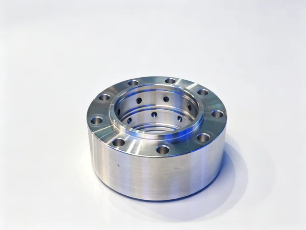
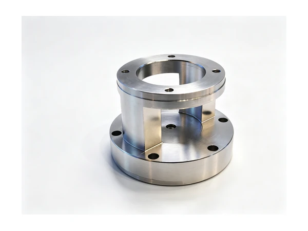
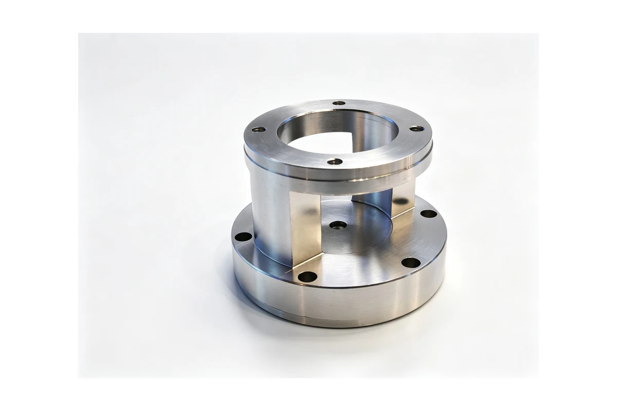
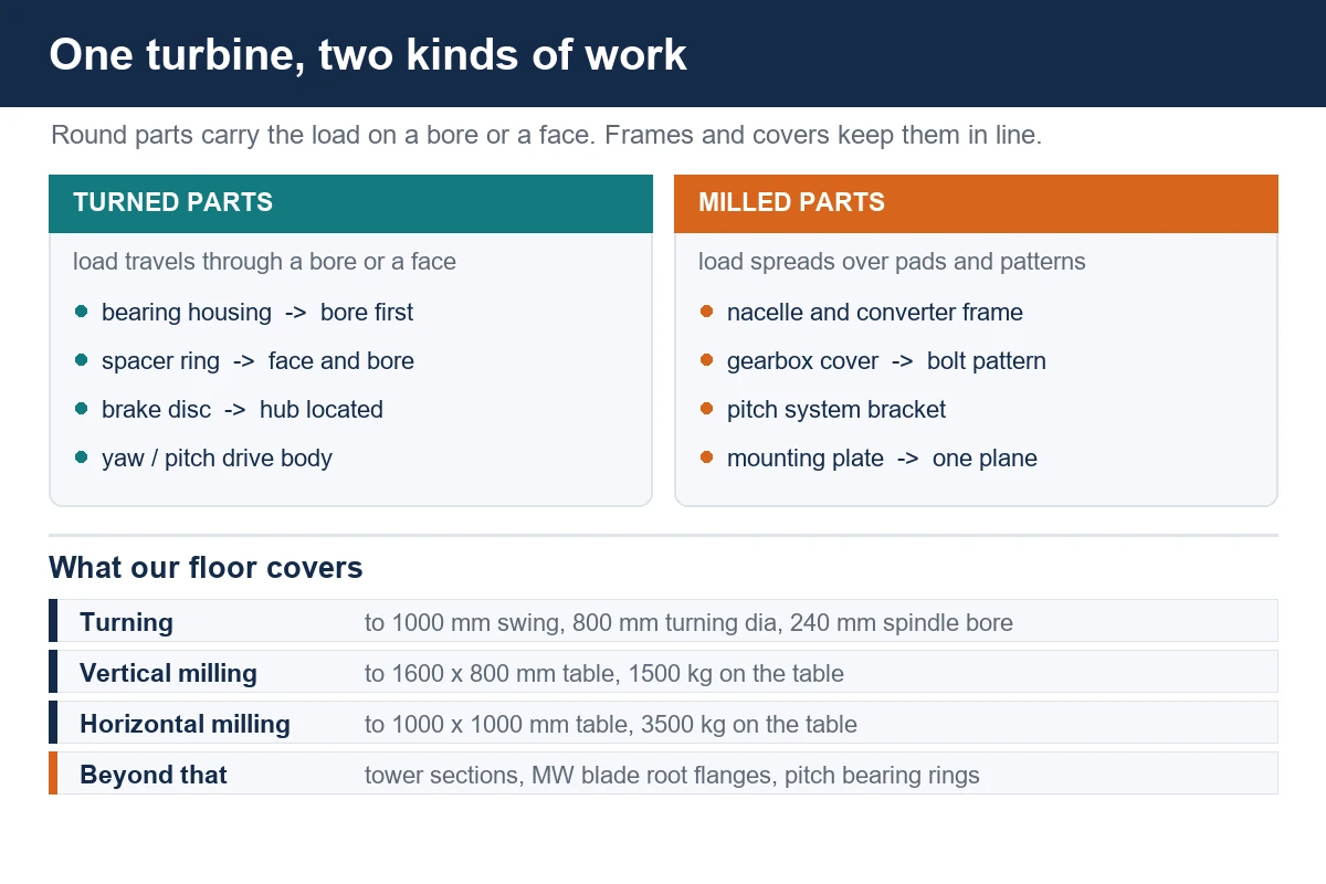
The sector divides into work that is round and work that is not, and that split decides the machine long before the drawing lands. On the round side we see main bearing housings and bearing seats for small and mid-sized units, yaw and pitch drive housings, the spacer rings and sleeves that sit behind a pitch bearing, brake discs for the yaw brake, generator end shields, and the shafts and ring gear blanks that go into a wind gearbox. On the milled side we see nacelle and converter frames, gearbox covers and inspection plates, pitch system brackets, yaw drive mounting plates, and the welded base structures that everything else is bolted to.
What makes the parts recognisable is not their shape but their function. Almost every one of them is a locating feature for something else: a bore that has to hold a bearing, a face that a disc rubs against, a bolt circle that has to line up with a mating flange 20 metres away, or a frame that has to keep four mounting pads in one plane. A wind part is usually a part that transmits a load and has to stay where it was put.
The batch sizes are what surprise shops that come from automotive. Twenty yaw drive housings, six gearbox covers, a hundred spacer rings. Nobody is running a million of anything, and that shapes the setup more than the material does: the fixture has to be worth building, and it has to be pulled out of the rack again next season when the same customer reorders.
Materials, and what each one does to the plan
Ductile iron, usually in the GGG40 to GGG60 range, is the material behind most bearing housings and drive housings on the drawings. It has the stiffness the housing needs and it damps the vibration that would otherwise travel into the structure. It also arrives as a casting, which means skin, draft, and variation between the first and the last of the batch. The first operation is normally to face one side and establish the bore, because a raw casting is not round enough to be the reference for anything.
Carbon and low-alloy steel cover the shafts, spacer rings, brake discs and anything fabricated. A 1045 or 42CrMo shaft turns cleanly once the heat treatment has been declared; if it is supplied pre-treated, the roughing pass has to get under a hardened skin rather than through it, and the finishing passes stay light. A flame cut or plasma cut blank for a spacer ring or a flange has a hard edge on the cut face, so the first pass is planned to clear it.
Structural steel is the whole story on the frame side. S355 plate and standard sections welded into a nacelle frame, a converter frame or a tracker bracket move when they are welded, and they keep moving for a while afterwards. Machining a weldment is not the difficult part; deciding when to machine it is. We cover that decision further down, and at length in the frame case study.
Aluminium turns up in the electrical and battery side of new energy work: busbar supports, covers, cooling plates, sensor brackets, and the light frame parts around a charging unit. It cuts fast enough that the limit is chip evacuation rather than the tool, and thin sections move more than steel once the fixture pressure is released.
The honest size question
Ask a shop about wind power and the first honest answer has to be about envelope, because the largest parts in a turbine are metres across and no catalogue machine touches them. Our turning range runs to a 1000 mm swing over the bed and roughly 800 mm finished turning diameter on the largest lathe we build, with a 240 mm spindle bore for bar work. Our largest vertical machining center takes a 1600 x 800 mm table rated at 1500 kg; the largest horizontal takes a 1000 x 1000 mm table rated at 3500 kg.
That covers the whole drive train of a small turbine and the drive train components of a larger one: housings, spacers, gears, shafts, brake discs, generator parts, drive mounting plates, and frames up to roughly the size of a small nacelle base. It does not cover tower sections, blade root flanges of a multi-megawatt machine, or the pitch bearing rings that sit between the blade and the hub. Saying that plainly saves a customer a wasted enquiry, and it tells the ones we can serve that we know where our own boundary is.
Where a lathe does the work
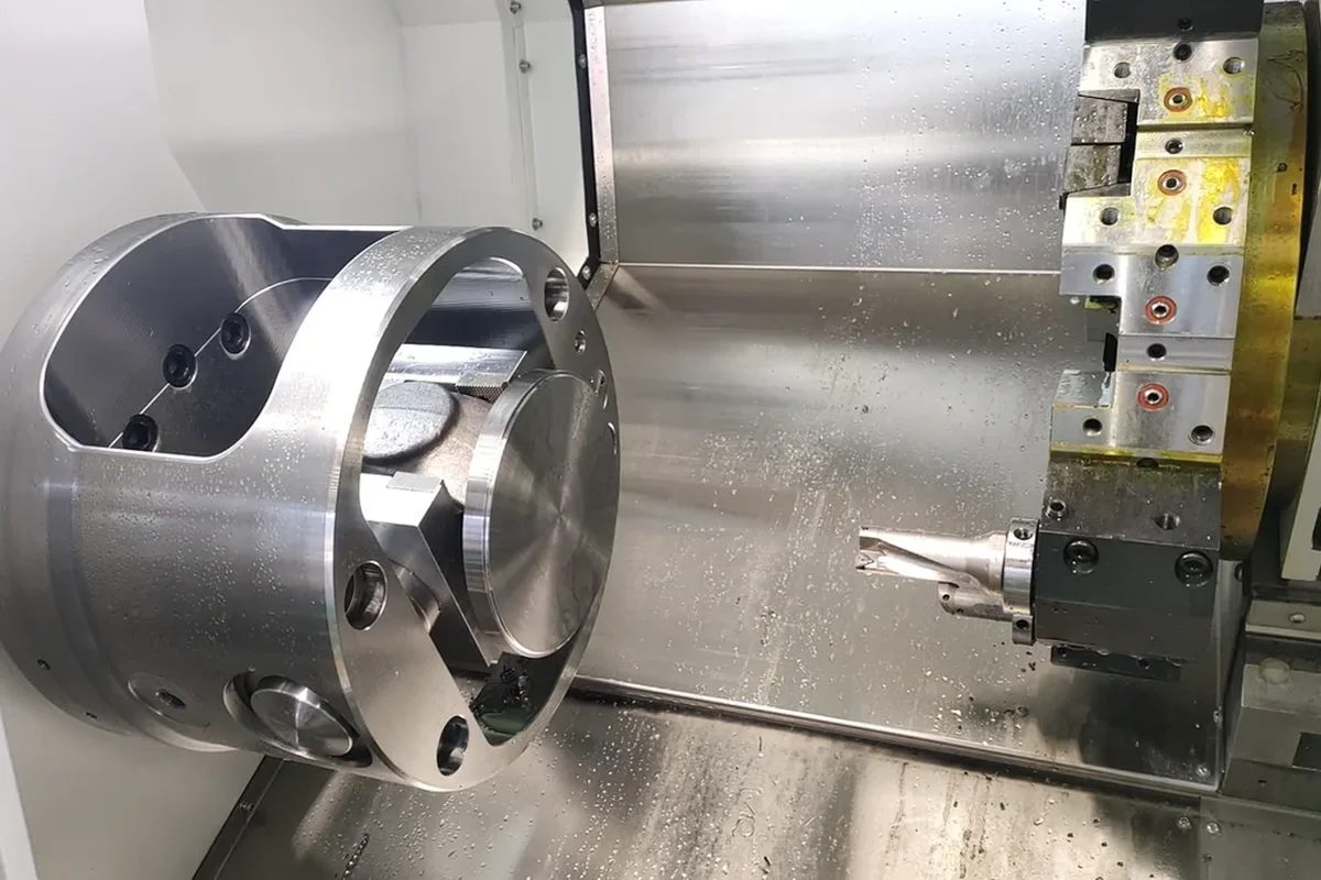
Bearing housings, spacer rings, brake discs and drive shafts are turning jobs, and the sequence on all of them is the same: establish the bore or the journal first, and let everything else follow it. A housing that has been turned from the outside in ends up with a bore that agrees with the casting rather than with the face, and on a bearing seat that is the difference between a bearing that stays put and one that creeps.
Our TCK6350B heavy-duty slant bed lathe swings 630 mm over the bed with a 96 mm spindle bore, takes bar up to 85 mm, and runs a 10 or 12 inch chuck on an 18.5 kW spindle with a horizontal 12 station servo turret. It is the machine we put most cast housings on, because a casting needs depth of cut on the first pass to get under the skin, and a slant bed lets the chips fall clear instead of packing under the work.
Longer and larger turning work moves to the TCK80D-1500, which swings 850 mm over the bed, turns 700 mm and takes 1450 mm of cutting length, with a 120 mm spindle bore and a tailstock for shaft work. For the largest discs in the range, the QK1322 takes the swing to 1000 mm with a 240 mm bore and a 1600 mm Z travel, which is enough to face and turn a flange ring that will not fit anywhere else on the floor.
Where a machining center does the work
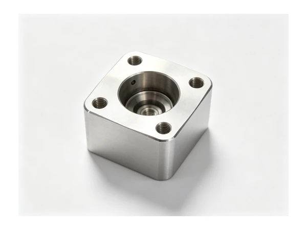
Everything that is not round goes to a mill, and on wind parts that is often most of the geometry. A yaw drive housing is a turning job with a pattern of mounting holes, dowel positions and tapped faces on several sides. A gearbox cover is a plate with a bolt pattern that has to match a casting. A pitch system bracket is a milled part from the first cut to the last.
For housings and drive bodies, a horizontal machine earns its place because four faces arrive without turning the part over. Our HMC800-DT carries an 800 x 800 mm table rated at 2500 kg with 1300 / 1150 / 1000 mm travels and a BT50 spindle, and the HMC1000 opens that to a 1000 x 1000 mm table at 3500 kg. On a cast housing that has already had its bore established on the lathe, the horizontal lets the mounting pattern, the dowel holes and the machined pads all come off the same setup as the bore, which is what keeps a drive housing sitting square in its frame.
Lighter and longer parts go vertical. The VMC1160 takes a 1200 x 600 mm table at 800 kg with a BT40 spindle, and the VMC1690 goes to a 1600 x 800 mm table rated at 1500 kg with 1600 / 900 / 700 mm travels and a BT50 taper. That is the range where welded brackets, mounting plates and inspection covers live, and where the part is long enough that support across its full length matters more than the table rating.
Where a part has geometry on faces that cannot be reached in two setups, a gantry five-axis machine removes the setups rather than the features. Our LH500 carries a 500 mm rotary table rated at 350 kg with 600 / 1000 / 600 mm travels and a 12000 rpm BBT40 spindle. It is the machine for a drive body with ports or pockets at an angle, and for any part where the alternative is three fixtures and three datums.
The operations that cause trouble
The bore against the outside. A cast housing that has been finished on the outside first has already committed the bore to the casting. Turn the first face, bore the pilot, then take the outside and the second face from that bore, and the housing holds its bearing in line with its mounting face instead of in line with the foundry.
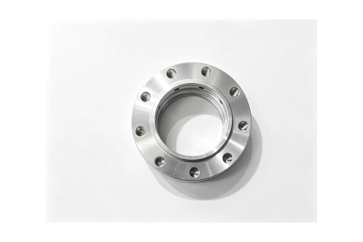
The bolt circle and the mating flange. On a housing or a spacer ring, the bolt circle is what mates with a part that was made somewhere else. Drill it from the finished bore and the finished face, and check the circle against the face rather than against the outside diameter. A pattern drilled from the rim inherits the rim.
Yaw and pitch drive meshing. The pinion and the ring or sector it meshes with are made as a pair on the drawing but not always machined as a pair. When the gear teeth are cut, the shaft, the bearing seat and the runout of the tooth circle are all one problem, and the tooth geometry follows the bore the same way everything else does. Our gear machining note goes through that sequence for a geared part.
Brake faces. A yaw brake disc is thin, wide and asked to run flat. Turning it in one clamping with the hub located on its bore is the only route that holds it, and the facing passes have to be light on a thin disc or the tool pressure pushes the disc away and the face comes out dished. The same problem appears on the brake discs we turn for other industries, which is covered in the notes on brake disc machining.
Weldments and when to machine them. A welded nacelle frame, tracker bracket or converter frame moves for days after welding. Machining it straight off the bench means the mounting pads are true on the day and out again by the end of the week. The practical answer is to weld, then let the frame settle, then machine the pads in one setup without unclamping it in between. Where a frame is too long for one setup, the datum for the second setup has to be a machined pad, not a welded edge.
Consistency across a small batch
Wind and new energy work is batch work in the hundreds, not the tens of thousands, and a batch that size is held together by the fixture and the first-off check rather than by the machine. The same fixture, the same datum, the same check on the bore, the face and the bolt circle at the start of the run, and a record that stays with the batch number. When a customer asks two years later why a replacement housing feels different, the record is the answer.
Two things drift on this work. Chuck jaws and fixtures lose their concentricity the moment they are re-bored for the next diameter, which is why soft jaws are kept with the job rather than with the machine. And a casting batch varies between the first and the last part, so the first-off check has to be repeated at the end of the run rather than assumed to hold for the whole pallet. Shops that treat the fixture as part of the part, instead of as part of the machine, are the ones that hold a reorder.
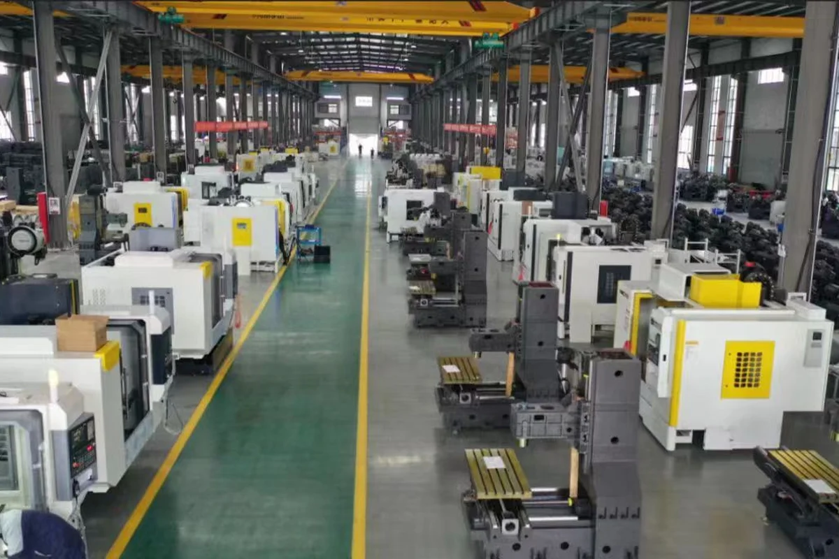
We build for that reality: a spindle sized for the depth of cut the material actually needs, a turret or a magazine with enough positions that the sequence does not have to be broken up, and frames stiff enough that a roughing pass on a casting does not move the work. The rest of the milled side of this work overlaps with what we do for construction machinery parts and for agricultural machinery parts, because a heavy welded bracket does not care which sector wrote the drawing.
New energy beyond wind
Solar tracking hardware looks like a smaller version of the same job. A slew drive housing is a cast or machined body with a bore, a gear seat and a mounting pattern; the tracker brackets and pile caps are weldments that need their mounting faces cut in one setup; the torque tube clamps are turned parts made in long runs. Battery and charging hardware brings a different mix: busbar supports and coolant plates in aluminium, sheet metal frames with machined mounting pads, and housings where the sealing face has to be flat enough for a gasket to work.
None of this needs a machine that wind work does not already need. It is the same turning for round parts, the same horizontals and verticals for bodies and frames, and the same discipline about which feature is the datum. That is why we treat wind, solar and battery work as one application rather than three.
What to put on the enquiry
An enquiry that arrives as a drawing plus a material plus a quantity gets a price. An enquiry that also says which face mates with which, whether the part has been welded and when, whether the casting has been proof machined, and what the part does in service, gets a setup plan as well. On this work the second one is worth the extra five minutes, because most of the cost sits in the setup and the fixture, not in the cutting time.
If the drawing calls out a bearing, say which one. If the part is one half of a pair, say so. If the part failed in service, send the failed part as well as the drawing, because the wear pattern usually says whether the problem was the bore, the face or the bolt pattern.
Questions we get
Can you machine a casting that has not been proof machined?
Yes, if the drawing carries an allowance and the customer accepts that the first operation establishes the datum. What we cannot do is finish a bore from an as-cast face and promise the casting has enough stock everywhere. Where a casting is critical, a proof cut on one face before finishing is the cheapest insurance in the job.
Should a welded frame be machined before or after stress relief?
After, where stress relief is available. Where it is not, the frame is welded, left to settle, then machined in one setup so the pads are true to each other. Machining a weldment the day it comes off the bench, and then again a week later, is a more expensive way of doing the same thing.
Do you cut the gear teeth or buy them in?
It depends on the part. Gears and pinions inside a drive body are usually cut in-house so the tooth circle and the bearing seat come off the same datum. Where a toothed ring is bought in and shrunk or bolted onto a hub, the machining on our side is the hub, the fit and the bolt pattern.
What is the smallest batch that justifies a dedicated fixture?
Around twenty pieces for a cast housing, less for a part that repeats every season and more for a one-off weldment. The test is not the quantity but the likelihood of the order coming back, because the fixture is only cheap if it is used twice.
Do you machine aluminium parts for the battery and charging side?
Yes. Aluminium covers, supports and coolant plates are normal work on our vertical machines, with the caveat that thin sections have to be supported and the fixture pressure eased before the last pass rather than after.
Next step
Send the drawing, the material and its condition, the batch size, and one line about what the part does. If it is a housing, tell us which bearing sits in it. If it is a frame, tell us whether it has been stress relieved. We will come back with the setup plan, the machine, and a price that includes the fixture where the batch justifies one. Contact Handemo CNC | Email: sales1@handemocnc.com | WhatsApp: +86 135 6320 3038