
CNC Machines for Valve and Hydraulic Parts
Explore CNC machining options for valve bodies, manifolds and hydraulic components, including HMC, deep-hole and mill-turn solutions.
Machining Valve Bodies and Hydraulic Components
Valve bodies, manifolds, cartridge housings and cylinder parts share one difficulty: the features that matter most are usually inside the part. Bores, spools, sealing faces and intersecting passages all have to line up with each other, and every one of them is measured after the part leaves the machine. Machine selection therefore follows the bore, not the outside shape.
This page sets out how to match a machine to valve and hydraulic work, what to check before quoting, and where each machine type reaches its limit. HANDEMO builds horizontal machining centers, vertical machining centers and mill-turn machines for exactly this class of part.
What Makes Hydraulic Parts Different
A hydraulic valve body is a pressure vessel with a precision bore running through it. Three things follow from that.
Bore geometry drives the process
Spool bores are long relative to their diameter, and their straightness and roundness decide whether the valve leaks or sticks. If the bore is deeper than about four times its diameter, tool deflection becomes the dominant error source and the process has to change: shorter overhangs, pilot holes, stepped boring bars, or a machine with a spindle sized for the bar you intend to use.
Cross passages break the bore
Every intersecting passage interrupts the cut. The tool enters and exits a void, which produces impact load, chip nesting and burrs on the far side. Deburring is not a finishing afterthought on these parts; it belongs in the process plan, and the machine needs enough axes and enough access to reach the intersections from a sensible direction.
Sealing faces are measured, not estimated
O-ring grooves, gasket faces and port threads carry the sealing function. Their position relative to the bore is what the inspector checks. That makes datum strategy the single most important decision on the drawing review, because a fixture that locates on the wrong face will produce parts that are accurate to themselves and wrong to the assembly.
Choosing the Machine by Bore and Access
Horizontal machining centers for multi-face bodies
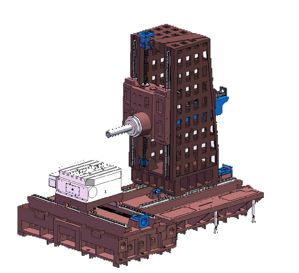
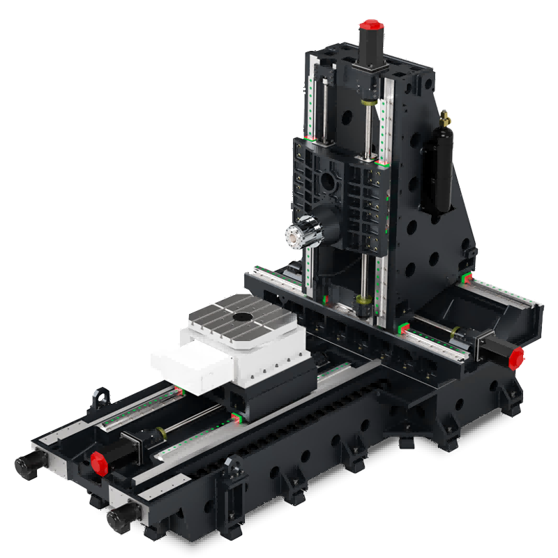
When a valve body or manifold needs work on four or five faces, a horizontal machining center removes the repositioning that a vertical machine would require. The spindle faces the part horizontally, chips fall away from the cutting zone rather than settling on it, and a rotary table indexes the part between faces without losing the datum. For bodies where the bores run through the long axis, this is usually the shortest route.
Two structural choices matter here. A T-type base with a travelling column gives a rigid, compact footprint for medium bodies. A multi-station or pallet configuration pays off once batch size is large enough that spindle idle time during loading becomes the constraint rather than cutting time. See horizontal machining centers for the full range, and deep-hole boring and milling machines when bore depth dominates.
Deep-hole machines when depth is the limit
Once bore depth passes roughly five times diameter, standard boring bars stop being the answer. Deep-hole boring and milling machines provide the guideway, coolant pressure and tool access to hold a line through a long bore. The trade-off is reach on the other faces, so these machines are usually specified around one dominant bore family rather than general work.
Turning and mill-turn for rotational hydraulic parts
Cartridge housings, cylinder ends, pistons and gland nuts are rotational, and many of them carry cross holes, flats or ports that would otherwise need a second operation. A mill-turn machine with a powered turret and Y-axis completes the part in one setup, which protects the relationship between the turned diameter and the cross feature. Where the part is purely rotational and volumes are high, a slant bed lathe is the more economical choice.
Vertical machining centers for plates and covers
Manifold plates, subplates, end covers and valve blocks that are essentially flat with features on two faces fit a vertical machining center well. The limitation appears when the part needs accurate work on the side faces, because each repositioning reintroduces the datum error the part cannot tolerate.
The Questions That Decide the Quote
Machine recommendations are only as good as the information behind them. These are the points that change the answer.
Bore specification
Largest and deepest bore, diameter and depth, tolerance band, roundness and straightness requirement, and whether the bore is through, blind or stepped. A single deep bore with a tight straightness call can move a part from a horizontal machining center to a dedicated deep-hole machine on its own.
Material and blank condition
Cast iron, ductile iron, steel, stainless and aluminium all behave differently on interrupted cuts. Whether the blank is a casting with variable stock or a pre-machined block changes the number of passes, the tooling and the cycle time estimate. Sand inclusion in castings is a common cause of underestimated cycle time on valve bodies.
Batch size and repeat pattern
One-off, small batch and high-volume production lead to different answers. Small batches justify a flexible machine with quick changeover; high volumes justify pallets, multi-station fixtures and automation. Quoting a high-volume part on a single-pallet machine overstates the cost per part, and quoting a one-off on an automated cell overstates the investment.
Inspection plan
If the drawing calls out bore position relative to a machined face, that face has to be created in the same setup or the process needs a deliberate datum transfer. Knowing this before the fixture is designed prevents the most expensive kind of rework.
Process Notes for Valve and Manifold Work
Sequence the bore before the ports
Boring first and drilling the cross passages afterwards leaves burrs inside a finished bore. Drilling first and boring afterwards cleans the intersection but risks the drill wandering on the interrupted surface. The usual compromise is to rough the bore, drill the passages, then semi-finish and finish the bore, with deburring between the last two steps.
Chip control is a quality issue, not a housekeeping one
Cast iron fines pack into cross passages and score a spool bore on the next pass. Horizontal orientation lets gravity help; through-spindle or high-pressure coolant helps more. Either way the chip path belongs in the process plan.
Fixture rigidity shows up in the bore
A valve body clamped on thin walls will move when the bore is opened. Supporting the body near the bore line, and avoiding clamp force across an unsupported span, is often worth more to the finished tolerance than a machine upgrade.
Related Guides
These articles go deeper into the specific part families and the machine comparisons behind the recommendations above.
- CNC machining guide for hydraulic valve bodies - bore strategy, large valve bodies and fixture design
- Machining hydraulic valve bodies - part families and process routes
- Machining hydraulic cylinders - long bore and barrel work
- Pump and valve parts guide - housing and impeller families
- Machining pump housings - bore alignment across faces
- Case study: hydraulic manifold blocks in one setup
- Case study: hydraulic piston guide sleeve
- Case study: deep-hole boring on an HMC
- Valve body machining overview
More Application Guides
Handemo builds machines for each of these part families. Each guide covers what the part demands from the machine and how the process is sequenced.
Discuss Your Machining Project
Send HANDEMO your drawing, material, bore specification, batch quantity and inspection requirements for machine and configuration guidance.
Request a Project Review