
CNC Gantry Loader Automation
CNC gantry loaders for lathes and VMCs: part storage, grippers, turnover, blow-off and machine signal integration for unmanned machining cells.
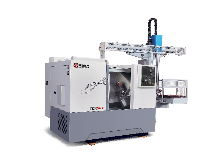
Gantry Loader Automation for CNC Machines
A gantry loader is the least disruptive way to remove manual loading from a CNC machine. It sits over the machine, travels on a fixed frame, and moves parts between a stock position and the workholding without occupying floor space beside the machine. For small and medium parts at steady volume, it is often the point where automation starts paying.
This page covers how to size a gantry loader, what the machine has to provide, and how to decide whether a gantry or an articulated robot is the better fit.
Where a Gantry Loader Fits
The loading time problem
On a lathe with a ninety-second cycle, twenty seconds of manual loading is roughly eighteen percent of capacity. The machine is not the constraint; the door is. A gantry loader removes that loss without changing the machine.
Footprint and safety
Because the loader travels above the machine, it does not need a fenced cell beside it. That matters in shops where floor space is already committed, and it simplifies guarding compared with a floor-mounted robot.
Part weight and geometry
Gantry loaders suit parts that a two-jaw gripper can hold reliably: shafts, discs, hubs, rings, small housings. Very heavy parts, parts with awkward geometry, or parts that need orientation in three dimensions are better served by an articulated robot.
Sizing the Loader
From the cycle time
The loader has to complete a full exchange within the machine's non-cutting window. That window is the sum of tool changes and rapid moves, and it sets the required travel speed and acceleration. A loader specified only by payload will often be too slow in practice.
From the part family
Gripper design follows the parts the shop actually runs, not the one part in the sample. A gripper that handles three part families is worth more than one optimised for a single job that ends next quarter.
From the buffer
Unattended running depends on how many parts the loader can queue. A small buffer gives short unmanned windows; a pallet magazine or a conveyor gives long ones. This is usually the difference between running through a break and running through a night shift.
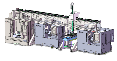
Gantry Loader Specifications: The Numbers Behind the Sizing
The sizing section above sets out which questions to ask. This one gives the figures those questions land on, because an enquiry that arrives as "we need a loader for a lathe" cannot be quoted, while one that arrives with payload, exchange time and buffer size can be quoted in a day. The ranges below are what we work to for lathes and vertical machining centres in the eight to twelve inch chuck class. Heavier cells scale up, but the logic does not change.
| Parameter | Typical figure | What it decides | Where it goes wrong |
|---|---|---|---|
| Rated payload | 10 - 250 kg gross, part plus gripper plus turnover unit | The heaviest part the cell can run | Gripper mass counted as part capacity; a 30 kg rating consumed by a 10 kg part |
| Axes | 2-axis (X, Z) or 3-axis (X, Y, Z), plus wrist rotation | Whether the part can be turned over inside the cell | Two-axis loader bought for a part that must be flipped; turnover station added later at extra cost |
| Exchange time | 6 - 12 s per part | Whether the loader fits the machine's non-cutting window | 12 s loader on a 10 s window; the loader waits, then the machine waits longer |
| Travel speed and acceleration | 1.5 - 2.5 m/s, 3 - 5 m/s squared | Exchange time over the real travel distance | Maximum speed quoted instead of acceleration over a 600 mm move |
| Repeatability | Plus or minus 0.05 to 0.1 mm at the gripper | Whether the part seats without an operator nudge | No positive stop in the workholding; no repeatability figure can fix that |
| Buffer | 8 - 12 parts gravity, 40 - 120 parts magazine | Length of the unattended window | Small buffer bought for a night-shift plan; the machine starves at 2 a.m. |
| Safety | Light curtain, interlocked power door, safe speed on the gantry axis | Whether the cell can run unmanned and legally | Loader fitted to a machine with a manual door; the retrofit dominates the cost |
Payload is gross weight, not part weight
A loader rated at 30 kg is rated for everything hanging on the arm: the part, the gripper body, the jaws and the turnover unit if there is one. A two-jaw gripper for a 250 mm diameter part typically weighs 15 to 25 kg on its own, so a 30 kg rating can be fully consumed by a 10 kg part. The number to send with an enquiry is the heaviest part in the family plus the estimated gripper mass, and then a margin on top. We size at 1.5 times that figure, because a gripper redesigned for a new part family always gets heavier, never lighter.
Exchange time is set by the machine, not by the loader
The loader only has the non-cutting window to work in. On a slant bed lathe with a 90 second cycle, tool changes and rapids leave 10 to 15 seconds. A loader that exchanges in 6 to 8 seconds fits; one that needs 12 seconds on a machine with a 10 second window never will, whatever its travel speed says. Acceleration is the figure that matters, because a 600 mm move at 4 m/s squared beats a longer move at a higher top speed. Ask for the exchange time over the actual travel distance, not the maximum speed on the sheet.
Repeatability, and why the loading position is a machine feature
Gantry loaders hold plus or minus 0.05 to 0.1 mm at the gripper, which is more accuracy than most workholding needs. What decides whether the part actually seats is the loading position inside the machine: a machined stop face, a chuck with a positive axial stop, or a fixture with a lead-in chamfer. Present a part to a three-jaw chuck with nothing to locate it axially and the loader will repeat to a tenth of a millimetre while the part still sits wherever the jaw pressure puts it. The stop is a machine modification and belongs in the project budget from the start. On parts where gripper force itself deforms the workpiece, the limits are covered in machining thin-wall parts.
Buffer size is the unattended window, written as parts
The buffer is what converts a loader into an unmanned cell, and the arithmetic is direct. At a 90 second cycle an hour of running is 40 parts, so a six hour unattended window needs 240 part positions. A gravity roller buffer at the machine holds 8 to 12 parts and buys a coffee break. A pallet magazine or a chain conveyor holding 40 to 120 parts buys a night shift. Most shops that end up disappointed with a loader bought the small buffer, so decide the unattended window first and let the buffer size follow from the cycle time. Typical loaded families, such as transmission shafts, run at volumes where this difference is the whole business case.
Safety is a light curtain and a power door, not a fence
Because the loader travels above the machine, the guarding is usually a light curtain across the load station plus an interlocked door on the machine, rather than a full perimeter fence. That is cheaper and it keeps the floor clear, but it puts two requirements on the machine: the door must be power-operated and interlocked to the loader controller, and the load station must be outside the operator's reach while the gantry is moving. A cell validated to the machinery directive with a light curtain, a door interlock and a safe-speed limit on the gantry axis is the normal configuration. A loader added to a machine with a manual door is a retrofit, and the retrofit is the expensive half of the project.
If the choice is still open between a gantry and an articulated arm, the four decision points are set out in gantry loader versus robot. Where the parts are large enough that the machine itself changes, see gantry or vertical machining centre.
What the Machine Must Provide
Mechanical interface
An automatic door, a defined loading position inside the work envelope, clearance for the gripper, and a workholding arrangement that accepts a part without manual intervention. A chuck that needs a manual jaw change defeats the purpose.
Control interface
The machine control needs a handshake: door open, part clamped, cycle complete, fault. Most current controls support this through standard IO or a fieldbus; older machines may need a retrofit, which is worth costing before committing.
Chip and coolant management
Automatic loading runs the machine harder and longer. Chip conveyors, coolant tanks and filtration sized for manual operation become the bottleneck when the machine runs unattended.
Data Needed for a Proposal
Machine data
Machine model and control, work envelope, door type, available IO, existing workholding, and the position of the machine relative to stock and finished-part locations.
Part data
Drawings, weights, material, the range of diameters and lengths, and how many distinct part families the loader must handle. A worst-case part in each family defines the gripper.
Production data
Shift pattern, target output per shift, acceptable unattended running time, and how operators will replenish the buffer. A loader that runs out of stock at 2 a.m. has not delivered unattended production.
Process Notes
Standardise the workholding first
Automation multiplies whatever the workholding does. If jaw changes are frequent and manual today, they will block the loader tomorrow. Standardising to a small number of chuck jaw sets is usually a prerequisite, not a follow-up.
Measure before and after
The justification for a loader is a number: parts per shift before and after. Establishing that baseline before the installation is the only way to verify the investment afterwards.
What a Gantry Loader Costs and What It Returns
The purchase price of a gantry loader is the smaller half of the cost. The larger half is the workholding standardisation, the door and fixture modifications on the machine, the safety validation and the downtime while the line is being commissioned. A shop that budgets for the loader alone will find the project runs 40 to 70 percent over before it is producing parts.
On the return side, the arithmetic is straightforward once the numbers are honest. Take the manual load and unload time per part, multiply by the parts per shift, and that is the capacity the loader recovers. A lathe with a 90 second cycle and 20 seconds of manual handling recovers roughly 18 percent of the shift, which on a two-shift operation is close to half a machine. That recovered capacity is the entire business case; everything else is detail.
The second return is the unattended window. If the buffer holds enough parts for six hours and the shop runs two shifts, the machine can run through the night and through breaks, and that is often a 30 to 40 percent output gain on the same floor space with no new machine. This is where the buffer sizing decision pays for itself, and it is the argument that most convinces a shop owner who is already at capacity.
The costs that get missed are the ones that appear after commissioning. Gripper jaws wear and need replacing; a jaw set per part family is a recurring cost. The automatic door mechanism on the machine becomes a maintenance item. The control handshake needs occasional attention when either side is updated. None of these are large individually, but they need to be in the operating budget from the start rather than discovered later.
Payback is usually quoted in months of recovered capacity, and for a single-machine cell at steady volume it typically lands between 12 and 24 months. Below a certain volume the loader never pays back, and the honest answer to a shop running short batches with frequent changeovers is that the money is better spent on a second machine or on reducing setup time. A loader makes sense when the parts are stable, the volume is steady, and handling is the constraint - not when the constraint is variety.
Gantry Loader or Robot: The Decision Points
The choice between a gantry loader and an articulated robot is decided by four questions, and the answers usually point clearly one way.
The first is where the parts come from and go to. A gantry loader travels on a fixed frame over the machine, so it serves a defined stock position and a defined finished-part position with no floor space between them. A robot needs a reachable envelope around the machine, which means floor space and fencing. In a shop where the floor is already committed, the gantry wins on that point alone.
The second is part orientation. A two-jaw gripper holds a part in one orientation and cannot re-orient it without a turnover station. If the parts must be presented at different angles - loaded one way into a CNC slant bed lathe and another way into a mill, or flipped between operations - an articulated robot with six axes does that without extra hardware, and a gantry needs a turnover unit that adds cycle time and a failure point.
The third is part weight and size. Gantry loaders suit shafts, discs, hubs, rings and small housings that a two-jaw gripper holds reliably. Very heavy parts, awkward castings or parts that need three-dimensional orientation belong on a robot. Trying to force a heavy or awkward part onto a gantry gripper is how projects end up with a loader that can only run half the part family. Where the part needs turning between operations as well as handling, a mill-turn machine removes the second load entirely and simplifies the whole cell.
The fourth is how many machines the system serves. A gantry can be built long enough to travel over two or three machines in a line, loading each in turn, which is efficient when the machines run the same part family in sequence. A robot serving multiple machines needs to travel or needs a rail, and the cost curve crosses over quickly. For a single machine, the gantry is usually the simpler and cheaper answer; for a flexible cell with several machines and varied parts, the robotic machine tending layout is the better fit.
Commissioning a Loader Without Losing Production
The installation is where most automation projects lose the time they promised to save. A gantry loader cannot be tested without the machine, and the machine cannot run production while the loader is being integrated, so every day of commissioning is a day of lost output. Planning that window properly is worth as much as the equipment choice.
The sequence that works is to standardise the workholding and the part program before the loader arrives. The gripper is designed around the parts the shop actually runs, and if the chuck jaws are still being changed by hand for each family when the loader is delivered, the loader will sit idle while the shop finishes a job it should have done first. Doing the workholding work up front costs weeks and saves months.
Commissioning should be staged: dry cycle with no parts, then single-part cycles with an operator present, then a full shift with the operator watching, then unattended running with the operator on call. Skipping a stage is how a loader crashes a machine on its first unattended night. The dry cycle catches the geometry errors; the single-part cycles catch the gripper and handshake errors; the watched shift catches the faults that only appear after an hour of running.
The measurement that matters is parts per shift before and after, taken over a full week rather than a good day. A loader that improves the best day but not the average week has not delivered; the unattended window is what the investment was for, and the average week is where that window either exists or does not. Establishing the baseline before installation is the only way to prove the result afterwards, and it is the first thing to do, not the last.
Related Guides
- Slant bed CNC lathe explained - the machine a gantry loader most often serves
- Machining transmission shafts - a typical gantry-loaded part family
- Machining thin-wall parts - where gripper force becomes critical
- Machining bushings, sleeves and rings - high-volume ring work
Discuss Your Machining Project
Send HANDEMO your machine model, part drawings, weights and shift pattern for gantry loader sizing and integration guidance.
Request a Project Review