CNC Machining Guide for Bearing and Flange Housings
A bearing housing is the part everyone forgets until it squeals. It does not drive anything and it does not move, yet it decides whether a shaft turns quietly for ten years or shakes itself loose in six months. The housings we see are usually simple to look at and awkward to make: a bore that has to run true, a flange or mounting face that has to sit flat against a machine frame, bolt holes that have to line up with someone else's casting, and on the larger sizes a wall thin enough that it moves when you clamp it. This article covers how Handemo machines bearing housings and flange housings: the shapes, the materials, the machines we put them on, and the process order that keeps the bore, the face and the bolt pattern working together instead of fighting each other.
What a Bearing Housing Needs
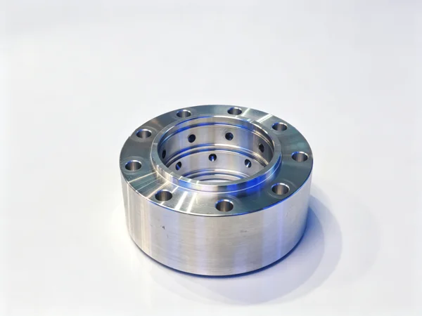
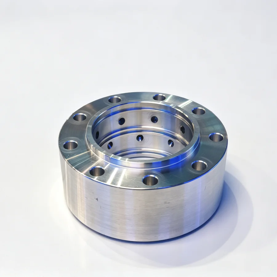
A bearing housing is the stationary half of a bearing arrangement. It holds the outer ring, keeps the shaft on its axis, and transfers the load into the machine frame. The family is wider than most people expect. A flange bearing housing bolts to a face and carries a shaft parallel to that face. A plummer or pillow block housing sits on a base and carries the shaft above it. A machined round housing drops into a bored seat. A split housing does the same job in two halves so it can be assembled around a shaft that is already in place. Gearbox end covers, motor end bells, pump bearing brackets and roller press chocks all belong to the same family.
Whatever the shape, the same handful of features decide whether the part works. There is the bearing bore with its shoulders and its retaining arrangement. There is the mounting face or flange that has to sit flat and stay flat so the housing does not distort the bearing when the bolts are tightened. There is the bolt pattern, which has to match the mating part. And there is the relationship between all three: the bore has to run true to the mounting face, and the bolt pattern has to be positioned from the bore rather than from the outside of a casting that was never meant to be a datum.
The critical feature is the bore-to-face relationship. A housing that is bolted down and then pinches the bearing is scrap, even if every dimension on the drawing was met in the free state. That is why so much of the work on this part is about setup and sequence rather than about cutting.
Materials We See on Housing Work
Cast iron is the traditional choice and still the most common. Grey iron housings machine easily, damp vibration well and hold their shape, which is why they dominate pillow blocks and gearbox covers. Ductile iron appears where the housing has to take shock or where a thin section would crack in grey iron. Cast aluminium shows up on lighter assemblies, on motor end bells and on anything where weight matters. Fabricated steel housings, cut and welded from plate, are common on larger equipment and on one-off work, and they bring their own problem: welding strain that has to be dealt with before the bore is cut. Steel bar and forged blanks are used for small, heavily loaded housings where a casting is not economic.
Two material habits matter here. First, castings arrive with a skin that is harder and dirtier than the metal underneath, so the first pass is not a finishing pass whatever the drawing says. Second, aluminium and light castings move with temperature and with clamping pressure, so the fixture has to hold the part without squeezing it, and the finishing cuts are taken with the part as free as the setup allows.
Choosing a Machine for Bearing Housings
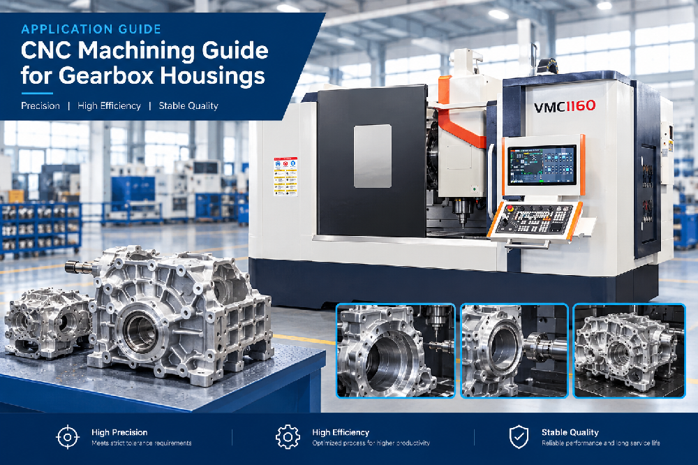
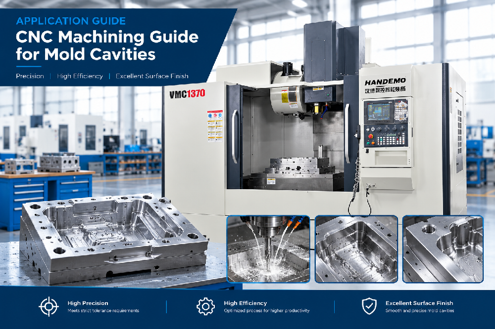
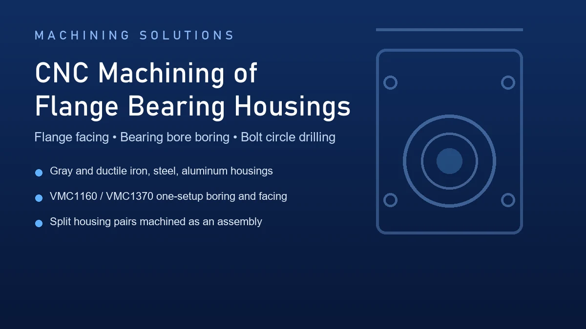
Most bearing housings are a boring job with a facing job attached, which is why a vertical machining center is the usual first answer. The part sits on its mounting face or in soft jaws, the bore is interpolated or bored from the top, and the flange face, bolt circle and any mounting feet are cut in the same setup. For the mid-size housings that make up most of this work, a machine such as the VMC1160 vertical machining center gives the table size and the travel to hold a 400 to 700 mm housing with room for the tool to clear the flange. Smaller flange units and end covers run comfortably on the VMC855, and large, heavy housings that will not sit still on a table are better handled on the bigger frames in the high-precision heavy-duty range, where the column and the base carry the weight without the machine leaning into the cut.
When the housing has work on several faces - a bore one way, a mounting face the other, and a bolt pattern that wraps around - a horizontal machining center earns its place, because the part is presented to the spindle from more than one side without being re-clamped. A housing with large bores on two opposing walls is the classic example, and a machine like the HMC630-DT cuts both walls from one datum. Where the volume is high enough to keep a spindle busy, the pallet-changing multi-station models do the same work with the load and unload happening outside the cutting time.
Some bearing housings are turning parts, not milling parts. A round housing or a flanged sleeve with a long bore and a machined outside diameter is cleaner on a lathe, where the bore and the outside diameter come off the same axis in one setup. Those parts run on the TCK6050 for the general range, and on the TCK6350B heavy-duty slant bed lathe when the housing is large and the wall is heavy enough to need a rigid machine under it. The choice between turning and milling a housing is usually decided by one question: which of the two features - the bore or the mounting face - has to be the datum. The machine that can hold both from one setup normally wins.

Establishing the Datum
On a bearing housing the datum is rarely the outside of the casting. Castings are drafted, they are not square, and they vary from part to part, so using the outside as a reference is how the bolt pattern ends up somewhere the mating part cannot reach. The workable references are the machined ones. On a housing that will be bolted face down, the mounting face is the datum: it is cut first, then the part is turned over onto it and everything else is positioned from that face. On a round housing that will sit in a bored seat, the machined outside diameter is the datum and the bore follows from it. On a flange housing the mounting face and the bolt circle are established together, then the bore is cut to them.
The order matters more than the individual choice. Whichever surface is picked as the datum has to be machined before anything is measured from it, and the datum has to be a surface that will still exist after finishing. Checking a bore against rough cast skin is how a housing ends up with a bore that runs true to nothing.
The Machining Sequence
Face the mounting face first
The first operation gives the part something to sit on. We face the mounting face or the flange face, clean up enough of the outside to hold the part, and then the whole job has a flat, machined reference. On a casting this operation also removes the skin from the surface the housing will actually bear against, which is the surface that matters for the joint.
Bore from the machined reference
The bearing bore is cut from the datum face, not from the outside of the casting. On a vertical machine this means the part sits face-down on the table or in jaws that have been faced in place, and the bore is interpolated or bored through. On a lathe it means the part is held on the machined face or the machined outside diameter and the bore is turned on the same axis. Either way, the bore and its shoulders are produced in the same setup as the face where possible, because that is the only way the bore is reliably perpendicular to the surface it mounts on.
Bolt pattern and mounting feet after the bore
The bolt circle, the tapped holes and any mounting feet are positioned from the bore, not the other way round. If the pattern is drilled first and the bore follows it, every cast variation in the outside of the housing is transferred into the relationship between the bore and the bolts. It is a small decision that decides whether the housing lines up with someone else's gearbox on the customer's bench.
Second-face work in one setup
Housings with features on two faces are planned so that as much as possible is cut without moving the part. Where that is not possible, the datum face is re-established on the second setup by indicating against a machined feature rather than against a stop that was set once. A housing that has been re-clamped twice with no datum carried across is a housing with a bore that runs true to nothing, however good the individual dimensions look.
Holding the Part Without Distorting It
The reason bearing housings fail in service is usually the fixture. A cast or aluminium housing is not rigid in the way a solid block is, and a chuck or a clamp that presses hard enough to be safe also presses hard enough to spring the bore. Cut the bore in that condition and it comes out round on the machine and out of round in the assembly.
We hold housings on their machined faces with soft jaws or a dedicated fixture that has been bored in place, so the clamping pressure lands on a surface that is already finished and the load is spread over it. Thin-wall and aluminium housings are cut with the clamp pressure kept as low as the job allows, and the finishing pass is taken with the part as close to its free state as the setup permits. Where a housing is too flexible to hold at all, it is machined on a face plate with the bore supported while it is cut, in the same way a thin ring is machined.
The second habit is temperature. Aluminium housings that come in from a cold store and are measured immediately will not measure the same after an hour in the shop, and the same applies to a casting that has just come off a heavy roughing cut. Roughing and finishing are separated so the part has settled before the bore that matters is cut.
Quality Checks
A bearing housing is checked as an assembly part, not as a set of unrelated dimensions. The bore is checked for size and for roundness at the position it will actually take the bearing, and the retaining shoulders are checked so the outer ring seats rather than rocks. The mounting face is checked for flatness and for squareness to the bore, because a face that is flat but not square pushes the bearing out of line when the housing is bolted down. The bolt pattern is checked against the bore with a gauge or a mate, and the whole part is measured with the clamping released and the part resting the way it will sit on the machine frame.
On a housing for a customer's own assembly, the check that catches the most problems is a trial fit: the mating part, the bearing, or the customer's fixture. That is the test that shows whether the bore, the face and the pattern are working together - the three things that no single dimension on the drawing describes.
Thinking About Your Bearing Housings
If you are quoting a bearing housing, three details on the drawing change the process more than any other. The first is which surface is the mounting datum and how flat it has to sit. The second is the wall thickness behind the bore, because that decides how the part can be held. The third is whether the bolt pattern is dimensioned from the bore or from the cast outside, because that tells us where the casting variation is allowed to land. Send those three and the batch size, and the machine choice usually follows on its own.
Handemo has been building machine tools in Tengzhou since 2008, across a plant of 220,000 square meters with more than 660 staff, and housing programs here start the same way any boring job does: prove the setup and the sequence on a trial part, then run the batch on the setup that was proven. Most of the bearing housing work that leaves the shop goes into pump sets, conveyor drives, fans and gear reducers, which means it is judged by whether the shaft turns quietly in the customer's machine, not by whether the drawing was met in the free state.
Frequently Asked Questions
What is the difference between a bearing housing and a flange housing?
A bearing housing in general is any stationary part that holds a bearing and locates a shaft. A flange housing is a specific type with a mounting flange: it bolts to a face and carries the shaft parallel to that face. Both are machined the same way, with the bore and the mounting surface produced from one datum, but the flange type adds a bolt circle that has to be positioned from the machined features rather than from the casting.
Should a bearing housing be machined on a lathe or a machining center?
It depends on which feature is the datum. If the bore and the outside diameter have to be concentric and the part is round, a lathe does both from one axis in a single setup, which is the cleanest route. If the housing has a mounting face, a bolt pattern and features on more than one side, a machining center holds the face as the datum and cuts the rest around it. On larger housings the deciding factor is often how the part can be held without being distorted.
Why does a bearing bore go out of round after machining?
Almost always because of clamping. A cast or aluminium housing is not rigid, and a chuck or clamp that holds it hard enough to be safe also springs the bore. The part measures round on the machine and out of round on the bench. The fix is holding on a machined face with soft jaws or a bored-in-place fixture, keeping clamping pressure low, and taking the finishing cut with the part as free as the setup allows.
Do you machine split bearing housings?
Yes. Split housings are machined in the assembled condition wherever the design allows, with the joint faces cleaned up first so the two halves are a known thickness apart, and the bore is cut through both halves together. That is the only way the bore is round when the housing is bolted together in service. The joint faces are marked so the halves go back together the way they were machined.
What materials can be used for a machined bearing housing?
Grey iron and ductile iron are the most common, cast aluminium for lighter assemblies, fabricated steel for large or one-off housings, and steel bar or forgings for small, heavily loaded parts. The material decides the setup rather than the sequence: castings need their skin removed before anything is measured from them, aluminium needs gentle clamping and a stable temperature, and welded housings need the welding strain dealt with before the bore is cut.
Get a Bearing Housing Machining Plan
Send us the housing - the mounting datum, the bearing bore and its shoulders, the bolt pattern and how it is dimensioned, the material, and the batch size - and Handemo will recommend the right machining center, lathe or horizontal machine and the process sequence to go with it. Contact Handemo CNC | Email: sales1@handemocnc.com | WhatsApp: +86 135 6320 3038
Related reading: CNC Machining Flange Bearing Housings covers the flange type in more detail, CNC Machining Guide for Gearbox Housings deals with the same datum problem on a bigger casting, and VMC vs HMC explains when a housing has enough sides to justify a horizontal machine. Housing work also sits under box and housing parts in our application pages.