Case Study: Machining a Gearbox Housing
An automotive gearbox housing is one of the most demanding workpieces a machine shop is asked to produce. It is a large aluminum or cast-iron box that has to hold the shafts of a transmission in precise alignment, support the gear set under load, and seal tightly enough to keep oil in and dirt out. Get any of those wrong and the whole transmission fails. This case study walks through how we machine one of these housings on a Handemo vertical machining center, the way we plan the setup, and the checks we use to keep a batch consistent.

The Workpiece at a Glance
The housing in this case is a die-cast aluminum box from a passenger-car transmission. It has two main bearing bores that carry the input and output shafts, a split face along the centre line where the case is joined to the cover, and a grid of small mounting bolts around the perimeter. Between the bores there are webs and ribs that keep the case rigid, and a thin wall section where the oil gallery runs.
Because the bearing bores have to share a common axis and the split face has to sit flat against its partner, the whole part is defined by a small number of critical features. Everything else is secondary. When we plan a housing, we treat those bearing bores and the split face as the heart of the job.
Why Alignment Is Everything
In a transmission, the power flows through the shafts that run in those bearing bores. If the two bores are not on the same axis, the shafts will bind, the gears will not mesh smoothly, and the unit will be noisy or fail early. If the split face is not flat, the seal will leak. So the machining problem is really a problem of holding position.
This is why we spend the first part of any housing job on datum control. The part may come from the die caster with a little draft and a little variation, but once we establish a clean datum and hold it through every operation, the finished housing stays within the envelope the customer needs.
Our Setup Strategy
We start by locating the part on the main bore and the split line, and then machine the top face as the reference datum. This top face is the one we use for every later operation that must line up. From that datum we:
- Bore the main bearing bores so the input and output shafts are on a common axis.
- Mill the bolt pads and the split face flat so the cover seats cleanly.
- Drill the mounting pattern and the oil passages.
- Machine the webs and rib faces that tie the structure together.
Keeping the part on one consistent datum through all of these steps is what protects the alignment. If we shifted the datum partway through, we would introduce a small error that would carry through the whole part.
Choosing the Right Machine
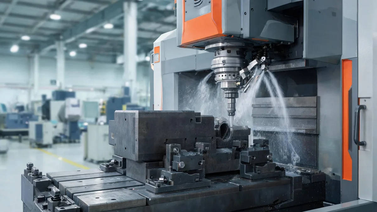
A housing is a larger workpiece, and it needs a machine with enough travel and stiffness to hold the bores true over the full length of the case. For a medium housing like this one, a Handemo VMC1160 is a strong fit. It gives us the travel to handle the casting, the rigidity to take stable machining cuts, and the repeatability to hold the bore alignment across a batch.
When a shop runs housings in higher volume, it often moves the work to a horizontal machining center. A horizontal machine lets the spindle reach the side of the part while chips fall away naturally, and a pallet system lets the operator load the next casting while the machine keeps cutting. That is where the throughput gains come from. But for a lower-volume job, or one where the customer wants flexibility, a vertical machining center with a fourth axis is the more practical choice.
Tooling and the Machining Passes
We rough the main bores and the split face first, removing most of the material so the part is close to size. Then we take a finishing pass only after the structure has settled. Castings are rarely perfectly stress-free; if you push them to final size in one hit, the finish can drift once the clamps are released. By leaving a small allowance and taking a light finishing pass, we keep the geometry stable.
For the bearing bores we use a boring bar, and we check the tool for wear at the end of each batch. A worn edge will show up as a taper or a poor finish, and on a housing that is not acceptable. For the bolt pattern we use a rigid tap or a thread mill depending on the hole size and the material.
Material and Cutting Considerations
Most transmission housings are cast from an aluminum alloy that is easy to machine but soft enough to gall if the tooling is not sharp. We run a sharp insert, a steady feed and a chip that does not rub and re-cut. For cast-iron housings the material is more abrasive, so we favor a coated insert and a slightly slower cutting speed to protect the edge.
Coolant matters too. On a large housing with a thin wall section, keeping the cut cool matters more than on a solid block. We use enough coolant to keep the tool point at a steady temperature, which protects the finish and the bore size through a long run.
Fixturing the Housing
How we hold a housing is almost as important as how we cut it. A large cast box is easy to distort if you clamp it too hard in one spot, so we use a fixture that locates on the datum we established and clamps evenly. This way the part does not twist under the cut.
The fixture we use for this housing locates on the main bore and supports the split line, so the clamping force goes into the body of the case rather than into a thin wall. We keep the clamping pressure even and we re-torque the fixture at the start of each batch, because a fixture can settle over time.
Common Problems and How We Avoid Them
Housings fail in fairly predictable ways, and most of them come back to a weak setup or a poor datum. The problems we see most often:
- Bore ovality or a taper, usually from a worn boring bar or a setup that is not rigid enough.
- A leaking split face, usually because the face was machined before the part settled or the datum shifted.
- Bolt holes that drift out of position, usually from a loose fixture or a poor reference.
- Poor finish in the bores, usually from chatter that comes from too light a setup or a spindle speed that is out of range.
Every one of these is solved by the same basics: a rigid fixture, a clean datum and a steady process. When we hold those, the predictable problems simply do not appear.
Quality Checks on the Line
Before a housing leaves the machine, we run a set of checks that matter for a transmission component:
- Bore alignment and ovality, measured with a bore gauge at both ends of the case.
- Flatness of the split face, checked against a straight edge or a surface plate.
- Position and size of the bolt pattern.
- Surface finish on the bore walls and the sealing face.
- That there are no burrs or chips left in the oil gallery that could reach the bearings.
These are the controls that turn a batch of castings into a batch of usable housings. They are not exotic; they are just the checks a responsible shop runs when the part has to work.
The Result
Once the process is dialed in, the housing holds the geometry the customer specified and the finish is consistent from the first part to the last in the run. The bore alignment stays true, the split face seats cleanly, and the bolt pattern lines up every time.
The gearbox housing work is a good example of why the right machine and a disciplined setup matter more than speed. A rigid machine, a clean datum and a steady process are what let a shop deliver automotive components that hold up in service.
Thinking About Your Own Parts
If you machine housings, casings, manifolds or other aluminum or cast-iron boxes, the same principles apply. Start with the feature that defines the part, hold it as the datum through every operation, and take a finishing pass only after the structure settles. The machine needs enough travel and stiffness for the workpiece, and the process needs a consistent plan.
If you are choosing a machining center for this kind of work, decisions about table size, travel and spindle power should come from the largest part you realistically make, not from the spec sheet alone. That is where a conversation with the builder helps. We are happy to talk through your parts and suggest a machine that fits the work you actually run.
If you would like to talk through a gearbox housing or any similar casting you run, our team is happy to help. Let us know the parts you machine and we will come back with the right machine options.